0
\$\begingroup\$

I read here about voltage dividing. Let's look at this image for the discussion:

enter image description here

Ok so we have 2 resistors in the circuit, and Vout is of lower voltage. But I don't understand - voltage is always a difference between two points. So, with respect to what point is Vout has a lower voltage?

If you say with respect to ground - then, why in this article it says:

Keep in mind not to use a voltage divider to reduce the voltage to supply a device or load because you have to remember that an external device will result in a parallel circuit with R2.

So actually if you take Vout, connect it to the + terminal of a device, and the - terminal to GND, the voltage of this circuit will be dependent on the resistance of the device. So what is this arrangement of voltage dividing good for?

I'm actually asking this because I want to supply my ESP8266 with power from a 9V battery, so I thought of using resistors to divide the voltage. But for this, I need to know the resistance of my ESP8266, which is not shown in the datasheet.

\$\endgroup\$
5
  • 1
    \$\begingroup\$ Voltage divider cannot be directly used to supply lower voltage to devices. The reason is same as mentioned in the question. Resistance of your IC is not a constant since the various devices inside the IC frequently turn ON and OFF thus changing the current drawn, even when voltage supplied is same. \$\endgroup\$
    – AJN
    Commented Jun 4, 2021 at 7:13
  • 1
    \$\begingroup\$ related question 1 related question 2 related question 3 \$\endgroup\$
    – AJN
    Commented Jun 4, 2021 at 7:16
  • 1
    \$\begingroup\$ The effective resistance of the esp varies greatlu depending on what it is doing, so a resistor divider is not a good solution. What you want is a voltage regulator. \$\endgroup\$
    – Kartman
    Commented Jun 4, 2021 at 7:16
  • \$\begingroup\$ Note - a 9V PP3 battery is not a good choice as they don’t have much energy. \$\endgroup\$
    – Kartman
    Commented Jun 4, 2021 at 7:19
  • \$\begingroup\$ What is it good for? It is good for supplying a voltage to devices which do not need a lot of current. For example, the input to and ADC. \$\endgroup\$
    – user57037
    Commented Jun 4, 2021 at 8:25

2 Answers 2

3
\$\begingroup\$

So actually if you take Vout, connect it to the + terminal of a device, and the - terminal to GND, the voltage of this circuit will be dependent on the resistance of the device. So what is this arrangement of voltage dividing good for?

It's good for driving very high resistances, where the load resistance has no significant effect on the output voltage. It is no good for supplying power to loads, especially variable ones.

I'm actually asking this because I want to supply my ESP8266 with power from a 9V battery, so I thought of using resistors to divide the voltage. But for this, I need to know the resistance of my ESP8266, which is not shown in the datasheet

No, do not do this.

A load like an ESP8266 does not have a constant resistance. It draws more or less current as its activity changes.

Use a regulator, that can supply more or less current as the load's demand changes, while keeping the output voltage constant.

A 9 v battery is not a good choice where the load current is significant, like that of an 8266.

\$\endgroup\$
2
  • \$\begingroup\$ Hi, thanks for the answer. Two questions: 1. Why isn't a 9V battery good? what do you mean by "load current is significant"? 2. What exactly do you mean by "driving very high resistances"? Can you give a circuit for example? \$\endgroup\$
    – YoavKlein
    Commented Jun 4, 2021 at 12:20
  • \$\begingroup\$ Most people mean PP3/6LR61 when they say '9 V battery'. That's a very low capacity battery, with very poor energy per cost. Their capacity is around 0.5Ah, a 10 mA load would last only 50 hours, 100 mA only 5 hours. 'Significant' gets meaning when you know how often you want to replace the battery, and how much you're going to spend on them. 'A very high resistance' would be a factor of 100 or 1000 higher than the resistors in the divider. For instance the non-inverting input of an op-amp, or the adjust pin of a regulator. \$\endgroup\$
    – Neil_UK
    Commented Jun 4, 2021 at 12:57
2
\$\begingroup\$

As Neil_UK's answer points out this arrangement is not good for power supply because it will change the resistance value if connected element is not high impedance element.

For power supply, you can use linear regulators like 7805 for 5V supply. You can also find 3.3V version of linear regulators. The higher voltage will be dissipated by mostly heat for linear regulators so it maybe more appropriate use switch mode regulators like lm2596. This regulators are more efficient and heat is not as problematic as in the case in linear regulators. But you should be careful about choosing capacitor and inductor values. There are cheap modules you can use which includes all capacitor inductor and resistance values for lm2596.

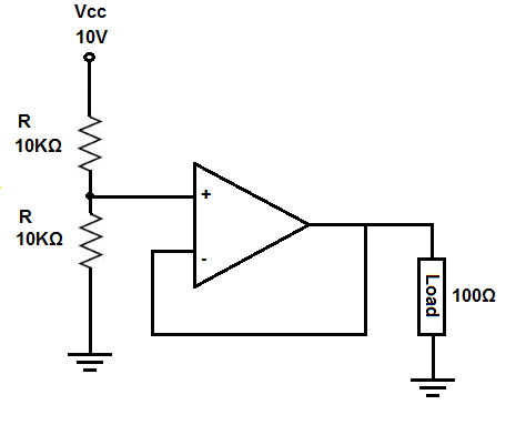
For your question about using resistor divider circuits they can be used for sensing circuits. For instance if you want to sense 9V with MCU, you can use voltage divider and since MCU digital pin will have higher impedance, there will be no significant change in resistance. But more appropriate usage will be by using voltage follower. Op-amp will have very high impedance and there will be no change. You can use it like;

enter image description here

Image Reference: link

\$\endgroup\$
0

Not the answer you're looking for? Browse other questions tagged or ask your own question.