0
\$\begingroup\$

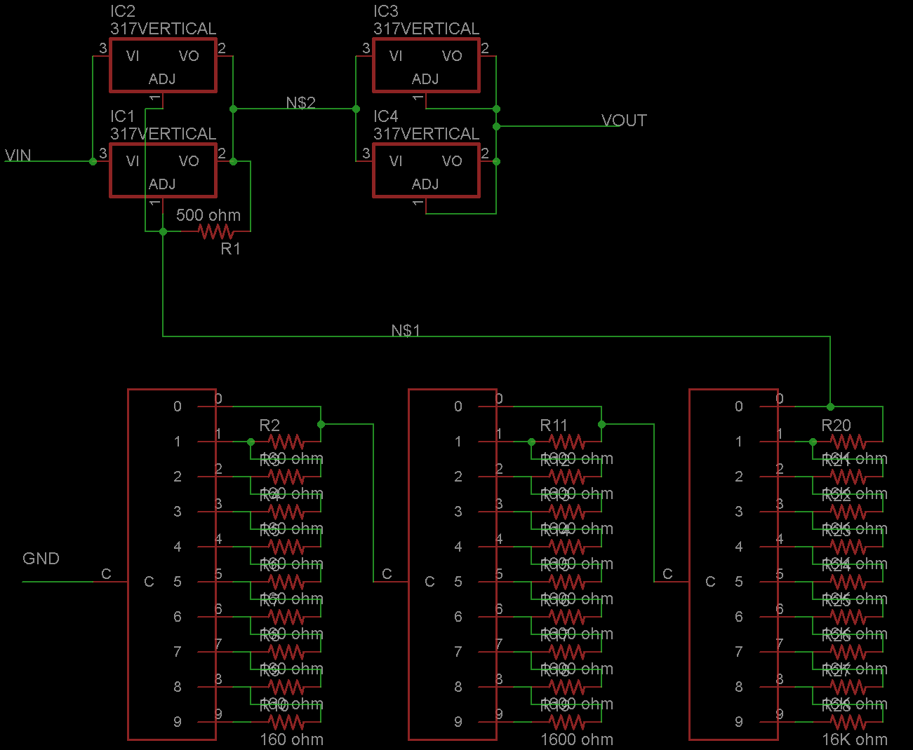
I'm making a power supply using some decade switches and resistors. The idea is to dial a voltage, much like a resistor substitution box, but get a voltage out instead of a resistance. I'm using the LM350 (high current version of LM317), but the LM317 voltage drop makes it nearly impossible to get a circuit that will make that work (set up like a standard resistor box, but with 160 ohms, 1.6K and 16K resistors at the three decades, and a 500 ohm between out and adj. To compensate, I'm currently thinking of just adding something to drop the voltage 1.5V-2V after the regulator, and compensate with a pot in front of the switches. The problem is, a simple diode drop is too inconsistent across temperature and current, and I can't seem to find another good solution. I was thinking setting up another LM350 in constant current mode, but set to something like 50A, or set to regulate to something like 100V so that it keeps the voltage as high as it can go, minus the drop. It wouldn't actually pass that much voltage or current, it would only be given maybe 24V at a couple of amps, but because it is set so high, it should try to bring the voltage as high as possible, but I don't know if that will work. The schematic is approximately what the final circuit would be (minus filtering caps and some diodes) The three boxes with resistors are rotary switches. The part I'm asking about is basically just if there will be a 1.25V drop between N$2 and VOUT. Thus, if whatever voltage is dialed by the rotary switches (as in a resistor substitution box) will be present at VOUT. schematic
TLDR: I need to drop a DC voltage by 1.5-2V at about 6A, the exact value doesn't matter, but it must be very constant (\$< \pm 0.02\text{V}\$) across reasonable temperatures and currents, and not overly complex or expensive. Is there any easy or "correct" way to do this?

\$\endgroup\$
5
  • 2
    \$\begingroup\$ Why don't you just switch in the proper resistances between the OUT and ADJUST pins which will result in the voltages you want at the OUT pin, and shunt the LM350 with a high current series pass stage? \$\endgroup\$
    – EM Fields
    Commented Jul 11, 2015 at 9:33
  • \$\begingroup\$ @EM Fields I'm not exactly sure what you mean by that. There is no set of resistors that will work correctly. For it to be linear, all resistors at each stage must be the same, but then, the output will be 1.25v too high. I fail to see where a series pass stage will help, the lm350 can push enough current and regulate well enough. As I understand it, a series pass would just regulate to some other voltage, much like a fixed linear regulator. Can you explain more specifically how this should be connected? \$\endgroup\$
    – jeduffy
    Commented Jul 12, 2015 at 7:30
  • \$\begingroup\$ I'll gladly do it if you'll edit your question with a schematic showing how you expect to regulate at around 100 volts or get 6 amperes out of an LM350, let alone 50 amperes using it as a constant current source without some off-chip help. \$\endgroup\$
    – EM Fields
    Commented Jul 12, 2015 at 13:03
  • \$\begingroup\$ @EM Fields The LM350 isn't actually regulating 100V or 50A. It will never have to take more than ~20V at 2.5A in. There will be 2 in parallel (with the necessary low-value resistors, though not included in the schematic). \$\endgroup\$
    – jeduffy
    Commented Jul 13, 2015 at 0:45
  • \$\begingroup\$ @EM Fields Sorry, I didn't know the "only edit comment after 5 minutes" thing, and accidentally saved the other comment without a fill explanation. The question wasn't about an lm350 operating outside of it's normal parameters, but what happens if the resistor ratio is set for 100V OUTPUT, but it is only supplied with 12V, or set for 50A output, but only supplied with 12V into a 30 ohm load. Would it drop the output to 10.75V, and if so, how precise and accurate would that drop be? \$\endgroup\$
    – jeduffy
    Commented Jul 13, 2015 at 0:52

2 Answers 2

0
\$\begingroup\$

The answer is simple - just connect the 'ground' end of your switched resistors to -1.25V, then the regulator's output will go down to 0V.

A stable -1.25V can be produced with an adjustable 3 terminal negative voltage regulator (eg. LM337) or two silicon diodes in series with a resistor, fed from a higher (negative) supply voltage. If you don't have a suitable negative voltage supply then you could use an ICL7662 (or equivalent) voltage convertor to produce it.

\$\endgroup\$
1
  • \$\begingroup\$ That's perfect! I can pretty easily make a stable -1.25V supply, so that will work perfectly. Never even though about it that way. \$\endgroup\$
    – jeduffy
    Commented Jul 15, 2015 at 3:13
1
\$\begingroup\$

I'm sorry to say I'm completely flummoxed.

Can we start at the beginning, please?

Here's how an LM350/LT1084 works:

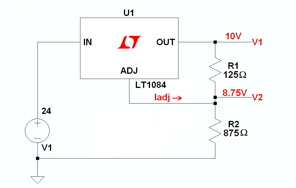
The way the regulator is designed is that you first decide what output voltage you want, (V1) then you arrange the voltage divider R1R2 so that with the desired voltage on U1's OUT pin the voltage on the ADJ pin (V2) is 1250 millivolts less. The current (Iadj) out of the ADJ pin will be less than 100 microamperes, so by making the current through R1R2 large enough, the drop across R2 caused by Iref can be swamped out and made negligible for most applications.

If not, then from the LM350 data sheet you can always use:

$$ \text{V1 = 1.25} \bigg ( 1 + \frac{R2}{R1}\bigg) + \text {Iadj R2 .} $$

To proceed without using the formula and assuming you want 10 volts out of the regulator and that you're willing to spend 10 milliamperes through the divider in order to reduce the error introduced by Iadj to around one percent, if we want a 1.25 volt drop through R1 with 10 milliamperes through it, from Ohm's law we have:

$$ R1 = \frac{Vadj}{Iadj} = \frac{01.25V}{0.01A} =\text{125 ohms.} $$

Then, to drop the rest of the 10 volts through R2, we can write:

$$R2 = \frac{10V - 1.25V}{.01A} = \text{875 ohms}$$

and we'll wind up with:

enter image description here

So there you have the basics.

Now for your switch...

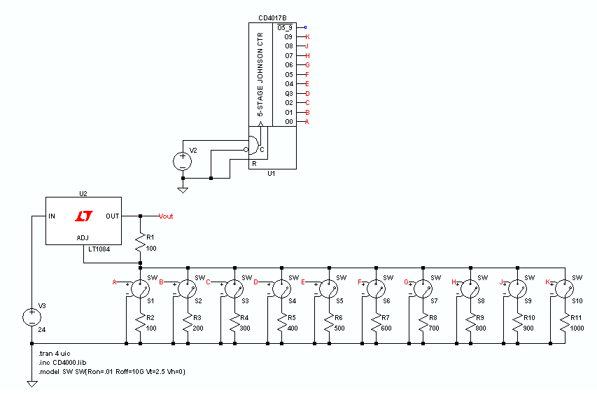
Following is an LTspice schematic which shows a single-pole 10 position switch as a series of voltage-activated switches driven by a counter with mutually exclusive outputs, ensuring that only one switch at a time will be turned on, exactly like your manually operated switch appears to function.

The counter is used to cycle through 10 states and to connect 10 different R2's to ground, changing the ratio of R1 to R2 at each step, which will change the regulator's output voltage in a planned way if the ratios are selected properly.

Notice particularly that, as opposed to your design, each switch position relies only on the ratio of the values of two resistors to determine the regulator's output voltage.

enter image description here

\$\endgroup\$
0

Your Answer

By clicking “Post Your Answer”, you agree to our terms of service and acknowledge you have read our privacy policy.

Not the answer you're looking for? Browse other questions tagged or ask your own question.