2
\$\begingroup\$

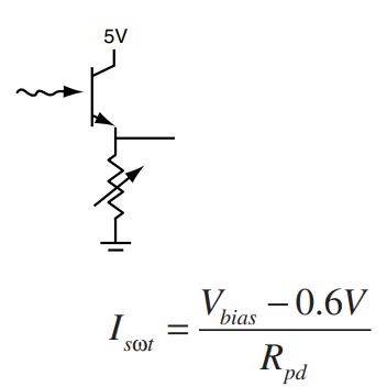
I decided to ask here for help, I am still new at electronics, I have been trying to figure out the definitions and graphs of this phototransistor, the PT1302 (datasheet here), my doubt is how can I calculate the value of a resistor below the emitter, the \$V_\text{out}\$ is connected to an Op-Amp, (from which I have successfully calculated all the resistors and values for components). From what I read, the given formula for the resistor in this particular arrangement is:

enter image description here

I know that the \$0.6V\$ correspond to the \$V_\text{CE}\$/\$V_\text{CEO}\$ in the datasheet, but I don't know if I am missing a formula to calculate Ic or the current or gain through collector to emitter.

And here is the matter, how can I compute \$R_1\$ or \$I_\text{C}\$ for the formula?. enter image description here
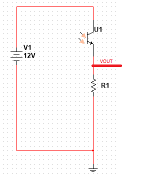
if I am not wrong \$R_1\$ is $$ R_1=\frac{V_\text{CC}-V_\text{CE}}{I_\text{C}}. \label{1}\tag{1} $$ I would really appreciate any feedback, comment, observation or example.

\$\endgroup\$

1 Answer 1

2
\$\begingroup\$

If the phototransistor is used as a switch, i.e. you do not want to use it for measuring the incident light intensity, then the right way to dimension the value of \$R_1\$ is to choose arbitrarily a maximum collector current \$I_\text{C}\$ (to say the truth, the choice is not entirely arbitrary: I'll give some detail on this in the notes), read from the datasheet what is the maximum value of \$V_\text{CE}=V_{\text{CE}_\text{(sat)}}\$ and then use formula \eqref{1} in the form $$ R_1=\frac{V_\text{CC}-V_{\text{CE}_\text{(sat)}}}{I_\text{C}} $$

Some notes on the "abitrary" choice of \$I_\text{C}\$.

  • While from the theoretical point of view the choice of \$I_\text{C}\$ is entirely arbitrary, from the practical point of view there are some limits. The most notable one is the maximum admissible value for this current, found in the "Absolute Maximum Ratings" table of the datasheet. For the device you are using, this is \$20\text{mA}\$: however, if you want to use it as a switch i.e. if you want to have \$V_\text{E}= V_\text{CC}-V_{\text{CE}_\text{(sat)}}\$ even at the lowest levels of incident radiation intensity, you should choose a far lower value: for example \$I_\text{C}\simeq 100\mu\text{A}\$ can be a good choice.
  • On the use as a "linear" radiation detector: if you are using the device for a linear application i.e. to measure light intensity, then the chosen value for \${I_\text{C}}\$ should be a half of the maximum collector current allowable by the power dissipation limits of the device. this is due to the fact that in such a way, you enhance the dynamic range of the output of the device.
\$\endgroup\$
2
  • 1
    \$\begingroup\$ Thanks a lot for replying, if I understand correctly, in this case is going to be used as a switch for my Opam comparator, the Vout of this phototransistor and resistor R1 will go into the non-inverting input, and through the inverting input a reference voltage of 7v, if I suppose that is the lowest level of incident radiation intensity Ic=100uA, hence R1 would be 70k Ohms (using Vcc as 12v), at the lowest, Vout of this phototransistor and resistor is going to be somewhat aprrox to 7v and if some extra irradiation enters it will make the vout increase, which will make the vout of my opam Vcc \$\endgroup\$
    – MtZandy
    Commented Jun 26, 2021 at 16:54
  • 1
    \$\begingroup\$ @MtZandy exactly. By setting to 7V the OpAmp/Comparator threshold you set a minimum level for turning it on: then you can use this datum in your design. \$\endgroup\$ Commented Jun 26, 2021 at 17:05

Your Answer

By clicking “Post Your Answer”, you agree to our terms of service and acknowledge you have read our privacy policy.

Not the answer you're looking for? Browse other questions tagged or ask your own question.