1
\$\begingroup\$

I intend to use an optocoupler to simulate a push button on a control card (I could measure 5V between pins but I don't know for sure if there is a pullup resistor in the card). Also the other way around, I'd like to "listen" to a 24 V output to detect voltage (and act as a logic gate for my 5 V microcontroller).

Optocoupler looks like a good candidate, as it keeps both circuits isolated.

I know I should limit currents for both the LED and the transistor, but how much? The datasheet tells about the absolute maximum limit (50 mA for both), but I can't find any "recommended" current for things to work nicely.

Basically I'm trying to calculate what the ideal resistors would be, but I don't know what to aim for (2 mA, 20 mA, 50 mA, anything?). I feel like hacking around could just lead to something that will break very soon if I use too much current.

Did I miss something on the datasheet?

\$\endgroup\$

5 Answers 5

3
\$\begingroup\$

The datasheet tells about the absolute maximum limit (50 mA for both), but I can't find any "recommended" current for things to work nicely.

The data sheet states a couple of values (other than the maximum value of 50 mA): -

enter image description here

So, if you are driving a circuit that requires more current on the output then, you use more current on the input. A good figure is 20 mA but, some folk will be interested in how little current is needed to activate the output transistor and, may be more inclined to move towards using 5 mA.

So, it's down to your application and what you want to achieve.

\$\endgroup\$
3
\$\begingroup\$

All the parameters are measured at 5mA LED current, so that is a hint for a good value.

As the transistor side is there to replace a push button, you just need to pull voltage as low as possible like a button would. Most likely the current is within reasonable limits but you can simply measure it with a multimeter.

\$\endgroup\$
1
\$\begingroup\$

Usually staying off by a factor 2 min. from maximum current rating is good rule of thumb.

Then your application current seems very very low: it is the simulation of a push button read in high impedance. So, thee current should be sufficient to avoid false triggering, and usually something in the order of 1 mA is enough. If you do not have problems of power consumption maybe some mA more it's even safer, but imho not needed.

You can even select a device with high gain from diode to transistor, to reduce diode current even more.

If you can supply some details more, we can be more precise, but I do not see critical points.

\$\endgroup\$
1
\$\begingroup\$

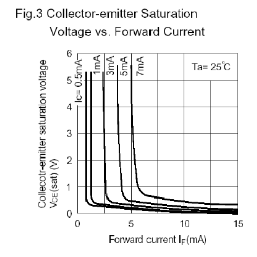
You can use Fig 3. to get a feel for how much LED current \$I_f\$ you need to get good output levels, depending on the amount of current you have to switch with your collector.
If you use a 10k Pullup with your 5V you will get a maximum \$I_C\$ of something like 0.5 mA, so you need at least 2 mA or 3 mA (at 25°C, better to oversize a little to be safe over the complete operating range).

enter image description here
Source: DPC‐817C datasheet

\$\endgroup\$
1
\$\begingroup\$

I usually work back from the Current Transfer Ratio and add a generous extra… for example, we use often the hcpl817 (an example, the procedure is general). Let's say a collector supply of 5V, and a pullup of 4.7 kOhm, would need about 1mA to pull down completely.

The datasheets indicates 50-600% CTR for not binned parts with a collector current of 2.5 to 30mA. Yep, 4.7 kOhms are too much, but 1kOhm is better with 5mA of collector current.

Since in the worst case CTR is 50% the minimum guaranteed is 10mA on the LED. Big discovery. In fact, to ease the process the datasheet also has the If vs VCEsat diagram which works more or less like a transistor one for biasing purposes.

They are quite easy to work with until you either a) go high speed or b) need to transfer an analog signal. There are both dedicated components and design techniques for these specific cases.

\$\endgroup\$

Your Answer

By clicking “Post Your Answer”, you agree to our terms of service and acknowledge you have read our privacy policy.

Not the answer you're looking for? Browse other questions tagged or ask your own question.