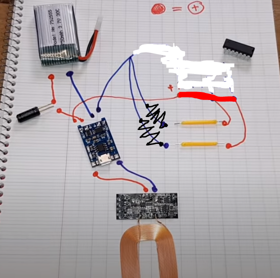
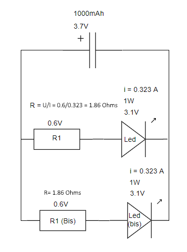
Your question seems mostly about the current-limiting resistor choice for the LEDs. The LEDs list the following specifications:
- Tension (forward voltage): 2.9 - 3.1V
- Puissance (power): 1W
There are countless other questions here and calculators on web sites about selecting the correct value of resistor for LEDs.
The TP4056 has a max charge voltage of 4.2V, which means that the LEDs will have this maximum voltage applied when the battery is being charged. This is therefore the value you should take into consideration to ensure that the LEDs never have too much current.
If they are 1W capable, then using Ohm's law, we can derive the maximum current that they tolerate:
$$I=\frac{P}{E}$$
1W / 3.1V = 0.323A or 323mA
Using the maximum voltage we expect to see, 4.2V, subtract the LED forward voltage to determine the voltage that will be across the current-limiting resistor:
4.2 - 3.1 = 1.1V
And then calculate the resistor value using Ohm's law, knowing its voltage will be 1.1 and current 323 mA:
$$R = \frac{E}{I}$$
1.1 / 0.323 = 3.41Ω
3.3Ω and 3.6Ω are common values of resistor. To err on the side of caution, I would use 3.6Ω resistors rated for the power that the resistor will need to dissipate:
$$P=I \times E$$
0.323 * 1.1 = 0.355 W
Therefore, a 3.6Ω 500mW (1/2 W) resistor would be recommended.
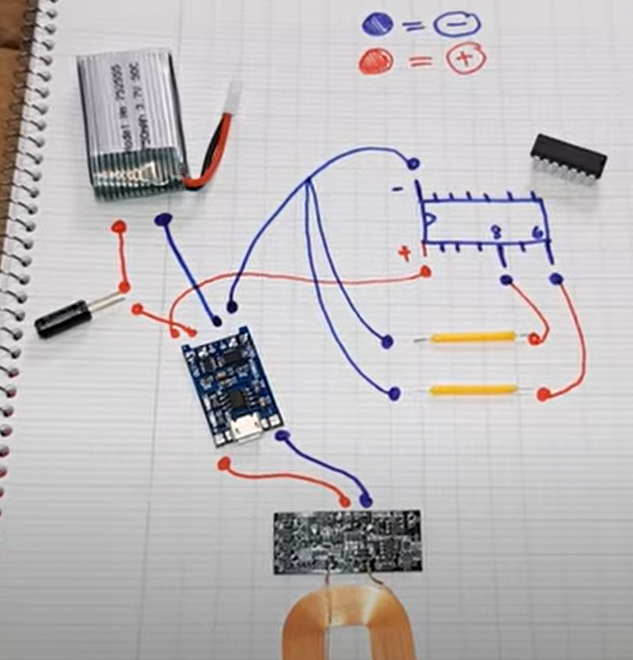
I do not know French, but from watching a brief clip of the video, I assume that the microcontroller (ATtiny) was utilized to add the flickering effect to the LEDs. Your project will just have constantly lit LEDs since you are omitting that portion. The comments in the video that you reference were likely pointing out that to drive that much current through LEDs, transistors should be implemented so that the microcontroller is not sourcing that much current.

As you can see here, the video shows a "schematic" where the LEDs are directly connected to the microcontroller, an ATtiny84, which can only source about 40mA on a GPIO pin:

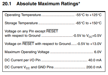
It may be worth noting that since the microcontroller can only supply 40mA, the LEDs shown in the video are likely operating much dimmer than they would without that limitation. You may want to recalculate the resistors for a 40mA current if they are too bright. If you do that, you will also gain greater run time from the battery (see below).
In any case, it is good to omit this from your project for now. Trying to drive LEDs with the microcontroller at ≥40mA would quickly damage it.
Next, you are correct that in having two LEDs in parallel, if each branch is at 323 mA, the total current (supplied by the charger or battery) would be 646 mA.
Finally, if the battery is 1000mAh then it can in theory supply 1000 mA for 1 hour, or 646 mA for 1.55 hours. Note that batteries often will have a rated capacity at a given discharge. For example, an alkaline battery may only provide its stated capacity at a low discharge (like 20 mA). Drawing more will result in reduced total capacity. However, a LiPo battery tends to be able to deliver higher current, so I think you could reasonably expect about 1.5 hour run time. If you were to limit current to 80mA (40mA per LED as mentioned above), run time would increase to perhaps 12.5 hours.
Good luck with your project.


