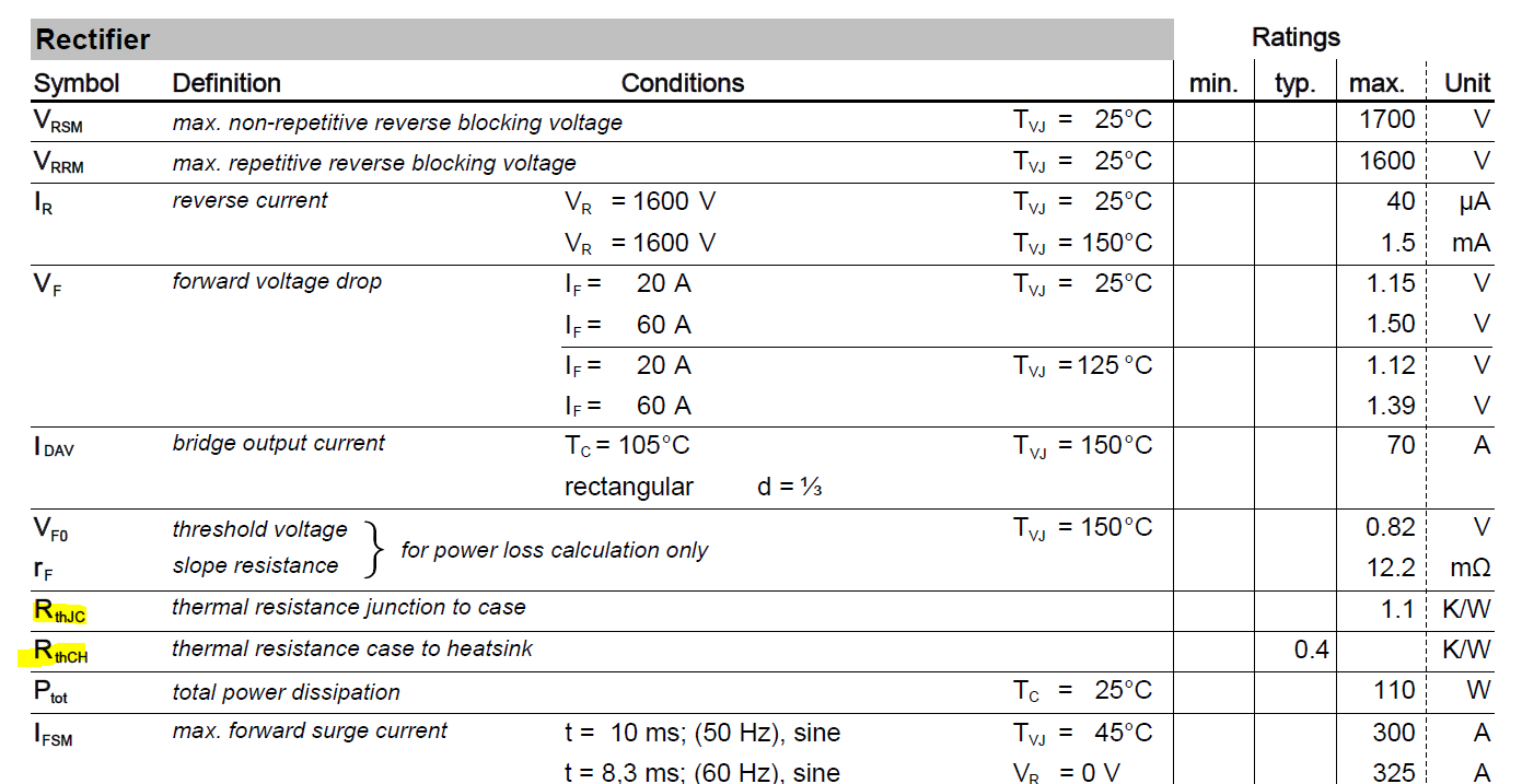
$$T_j = P_d\cdot R_\text{JC}+6\cdot P_d\cdot R_\text{CH} + T_\text{Heatsink}$$
Am I wrong?
If Pd is the individual diode power , it must be \$\Sigma ({P_1..P_6})\$, else the 2nd term is incorrect, which now must be Pd/6 * 6.
If Pd is total. Since, all 6 diodes conduct heat into any shared environment temperature rise effects of each part are cumulative thru every interface. Thus, if all indiviual thermal and electrical resistances are equal, the Pd is shared (ie. total power of the package.) and there is no 6x term in the equation.
$$T_j = P_d\cdot R_\text{JC}+ \cdot P_d\cdot R_\text{CH} + T_\text{Heatsink}$$ for Pd = all Power Dissipation
other info
It is not so obvious in 3 phase bridge rectifiers SHARE that the power dissipation in each diode, let alone ON at the same time.
For single-phase only 2 diodes of 4 on diagonals conduct at the same time, so the power-sharing duty cycle is 50% for each diode.
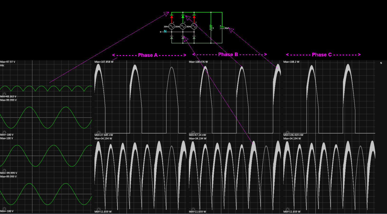
Consider \$3\phi Y\$ output, which is commonly used on transformer secondaries. As 3 cathodes from Neutral go to the -DC terminal.
Since Neutral is common to all 3 phases , it is only 1 diode drop away from -Vdc output terminal. Meanwhile the +Vdc terminal also has 3 Anodes in common to each Line phase. Thus 1st 3 diodes with Vf across all 3 diodes conducting a 3f rectified current the same current as the +Vdc diodes yet they only conduct for 1 / 3 duty cycle for power.
Since these tend to be discrete power diodes in car alternators, they must be thermally well bonded to overcome the 3:1 difference in power sharing for half of the diodes.
Although this is not the reason, the assumption in your formula is incorrect. We must assume all junctions are at the same average temperature , even though they did not reveal this secret.
My Bad assumption
If Y connections are asymmetric, then treat all 3Ph sources for DC as Delta output. Then each phase diode pair only conducts for 1 / 3 of the cycle to a resistive load. (neglect C loads for now)
Rule # 1 always define assumptions, as it can make an ass out of you and me. (; ;)
Although my assumptions were correct. The -Vdc diodes share current equally depending on these MUST be thermally bonded to prevent thermal runaway. Thus they share 50% of the Pwr total equally or 1/6th each, while the top 3 diodes also share 1/6th of the total power but rather than on all phases, just 1 phase at a time.
Ignore the tongue in cheek frequency,  Falstad's Sim requires you to define stray and reactance on all parts which are assumed to be pure resistive or ideal reactive components.
The correct assumption in this design is unlike 2-ph, 3-ph must be thermally well-bonded on the bottom 3 phases to avoid thermal runaway. It's a product of thermal, electrical resistance mismatch and power applied where near maximum, the loop can exceed a gain > 1 and cause thermal runaway in 1 of the bottom 3 diodes.


