1
\$\begingroup\$

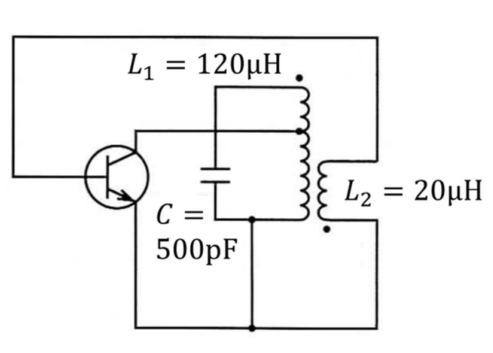
I've been searching for the exact name of the below circuit. I only that the below circuit is an LC oscillator circuit.

Can anyone tell me what it is, and tricks for searching the exact names of circuits?

Moreover I want to be sure that the oscillation frequency of the circuit is given by:

$$ f_{\text{o}} \approx \frac{ 1 }{ 2\pi \sqrt{ L_{1} \cdot C_{} } } $$

I thought that the most resembling circuit to the below circuit is a synchronous LC oscillation circuit.

If the part of the coil above the node (which connects between the wire of the collector and the coil) is just a wire, then I think that I can determine that the shown circuit can be said as a (collector?) synchronous LC oscillator circuit.

enter image description here

\$\endgroup\$
7
  • 3
    \$\begingroup\$ It's nothing without a power supply connection and proper transistor base biasing arrangements. So, until you have a working schematic (or details about where the diagram came from) you have basically nothing. \$\endgroup\$
    – Andy aka
    Commented Aug 30, 2021 at 14:07
  • \$\begingroup\$ It looks like a Hartley oscillator \$\endgroup\$
    – jay
    Commented Aug 30, 2021 at 15:17
  • 1
    \$\begingroup\$ It isn't a Hartley oscillator at all @jay \$\endgroup\$
    – Andy aka
    Commented Aug 30, 2021 at 16:39
  • \$\begingroup\$ Seems as a "blocking" oscillator. (period 120 ns, 50 ns pulse) ? L1 center tap. Added a 1k resistor ( emitter side) and power suply. "3" inductors ... :-) \$\endgroup\$
    – Antonio51
    Commented Aug 30, 2021 at 16:51
  • \$\begingroup\$ @Andyaka, Thanks, sincerely. :-) What would you name it then, if you do? \$\endgroup\$
    – jay
    Commented Aug 30, 2021 at 16:58

3 Answers 3

2
\$\begingroup\$

I don't know of any particular name that this configuration has other than "LC oscillator".

A nice article I found describing it is this one: LC Oscillator Basics

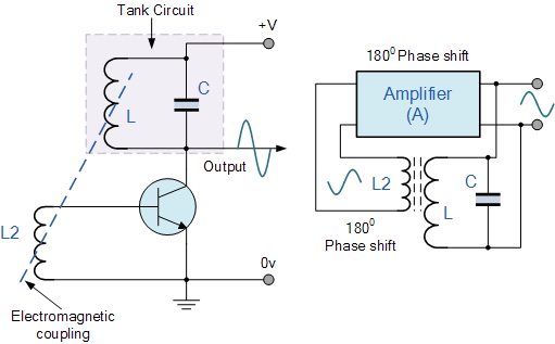
What you have here is a slightly modified version of the same circuit in that article, with a small modification to increase the loop gain. Your schematic is missing a voltage source connected to the top of L1.

To understand why this oscillates at the frequency \$ f_o = \frac{1}{2\pi \sqrt{ L_{1} \cdot C}} \$, you need to know two things:

  1. Why an LC "tank" circuit resonates at that frequency. Here's a nice article addressing this: Simple Parallel (Tank Circuit) Resonance. This is an easy read. It basically says that there's a frequency, called the "resonant" frequency, at which the capacitive and inductive elements have the same reactance, and will oscillate naturally at that frequency, as a child's swing will. And, similarly to a child's swing, the amplitude of the oscillation will increase if small inputs of energy occur at that same natural frequency.

  2. How feedback of the correct gain and phase is used to encourage oscillation. That's a bit more involved, and if the first link I gave (LC Oscillator Basics) doesn't do it for you, perhaps another allaboutcircuits.com article (actually a whole series) can help: Negative Feedback, Part 4: Introduction to Stability. This latter article is actually about how to make a system with feedback stable, but considering what you require for oscillation is intentional instability, it's actually the same topic, just viewed from another perspective.

A grossly inadequate summary of these two points might read like this: In a simple system with an amplifier (the transistor) and feedback (the transistor's base signal derived from an transformer-coupled version of the LC tank's voltage), maximum instability (oscillation) will occur at the frequency where that feedback is most "positive". See "Barkhausen stability criterion".

That is, where the signal fed back has the greatest amplitude, and whose phase is such that changes at the input (transistor base) are regenerative, causing the output (the collector) to change in a direction that further "boosts", or "reinforces" the initial input change.

Given that the output signal is the voltage across the LC tank, whose greatest amplitude occurs at its resonant frequency, and by feeding back a copy of that signal with the correct polarity back to the base, we deliberately violate the Barkhausen stability criterion, and oscillation will happen at the natural frequency of the LC tank, \$ \frac{1}{2\pi \sqrt{ L_{1} \cdot C}} \$.

\$\endgroup\$
2
\$\begingroup\$

In Europe it is probably named as Meissner oscillator while Armstrong is most common in English speaking countries.

https://en.m.wikipedia.org/wiki/Armstrong_oscillator

The qualifying point is the magnetic coupling. The resonating tank can be either on base/gate/grid or collector/drain/plate side. This mostly choosen to trim active device input and output impedances load to the L/C tank and in turn try to keep its Q high.

That's obviously a small signal equivalent circuit disregarding bias topics.

\$\endgroup\$
1
\$\begingroup\$

Harmonic Oscillators (Sinusoidal Oscillator) come in many different forms because there are many different ways to construct an LC filter network and amplifier with the most common being the Hartley LC Oscillator, Colpitts LC Oscillator, Armstrong Oscillator and Clapp Oscillator to name a few.

enter image description here

Source #1
Source #2

\$\endgroup\$

Your Answer

By clicking “Post Your Answer”, you agree to our terms of service and acknowledge you have read our privacy policy.

Not the answer you're looking for? Browse other questions tagged or ask your own question.