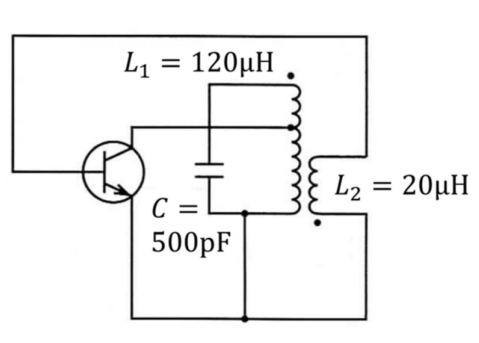
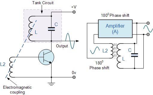
I don't know of any particular name that this configuration has other than "LC oscillator".
A nice article I found describing it is this one: LC Oscillator Basics
What you have here is a slightly modified version of the same circuit in that article, with a small modification to increase the loop gain. Your schematic is missing a voltage source connected to the top of L1.
To understand why this oscillates at the frequency \$ f_o = \frac{1}{2\pi \sqrt{ L_{1} \cdot C}} \$, you need to know two things:
Why an LC "tank" circuit resonates at that frequency. Here's a nice article addressing this: Simple Parallel (Tank Circuit) Resonance. This is an easy read. It basically says that there's a frequency, called the "resonant" frequency, at which the capacitive and inductive elements have the same reactance, and will oscillate naturally at that frequency, as a child's swing will. And, similarly to a child's swing, the amplitude of the oscillation will increase if small inputs of energy occur at that same natural frequency.
How feedback of the correct gain and phase is used to encourage oscillation. That's a bit more involved, and if the first link I gave (LC Oscillator Basics) doesn't do it for you, perhaps another allaboutcircuits.com article (actually a whole series) can help: Negative Feedback, Part 4: Introduction to Stability. This latter article is actually about how to make a system with feedback stable, but considering what you require for oscillation is intentional instability, it's actually the same topic, just viewed from another perspective.
A grossly inadequate summary of these two points might read like this: In a simple system with an amplifier (the transistor) and feedback (the transistor's base signal derived from an transformer-coupled version of the LC tank's voltage), maximum instability (oscillation) will occur at the frequency where that feedback is most "positive". See "Barkhausen stability criterion".
That is, where the signal fed back has the greatest amplitude, and whose phase is such that changes at the input (transistor base) are regenerative, causing the output (the collector) to change in a direction that further "boosts", or "reinforces" the initial input change.
Given that the output signal is the voltage across the LC tank, whose greatest amplitude occurs at its resonant frequency, and by feeding back a copy of that signal with the correct polarity back to the base, we deliberately violate the Barkhausen stability criterion, and oscillation will happen at the natural frequency of the LC tank, \$ \frac{1}{2\pi \sqrt{ L_{1} \cdot C}} \$.


