1
\$\begingroup\$

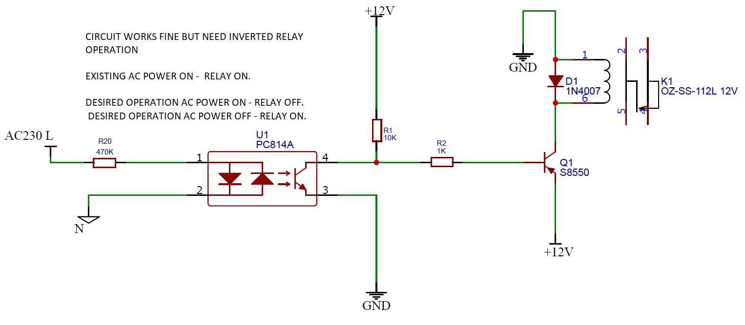
I have tried every possible way but was not successful for the operation required.

When AC Power 220V is fed to the PC814 optocoupler, the relay should turn off.

enter image description here

Please suggest modification in existing circuit to work as per desired operation.

Relay should be in ON when mains 230 AC to signal failure. It hould be OFF when MAINS 230AC available.

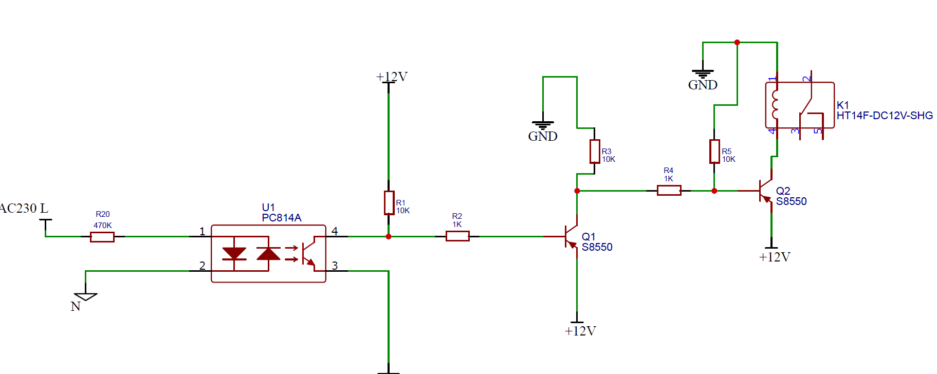
Modification that I had tried is as below image but it did not work.

enter image description here

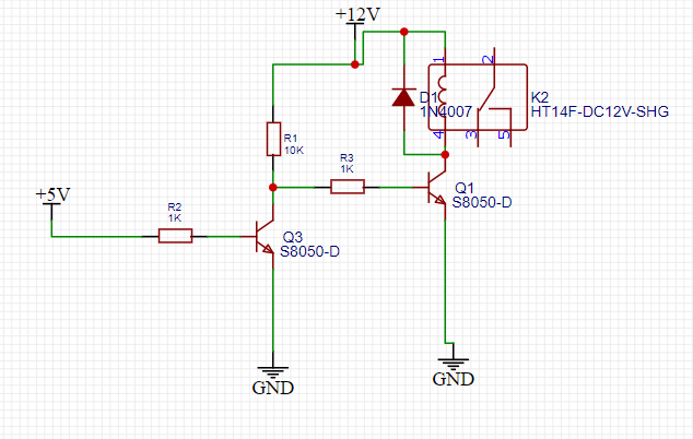
The modification that tlfong01 suggested working fine.

enter image description here

\$\endgroup\$
5
  • 1
    \$\begingroup\$ What possible ways have you tried? What parts of the circuit can be altered to make it work? For example can you change the relay type, or transistor type, or wiring between them, the resistor arrangement or values, or switcy the relay wiring to be low side driven? \$\endgroup\$
    – Justme
    Commented Sep 7, 2021 at 5:54
  • 1
    \$\begingroup\$ Please find updated post. I have shown modified circuit but did not worked. \$\endgroup\$
    – Kalpesh
    Commented Sep 7, 2021 at 6:01
  • 1
    \$\begingroup\$ In which way it did not work? In which way it does work then? I mean, the diode is now gone, so relay might destroy Q2, but also you use a different relay with NO and NC contacts so you could simply use the original circuit and use the new relay with the other set of contacts. \$\endgroup\$
    – Justme
    Commented Sep 7, 2021 at 6:09
  • 1
    \$\begingroup\$ Sorry forgotted Free Wheeling diode. Its actually there i missed in circuit diagram. See the moto of using Inverted relay is to save life of Relay coil. In simple way i could power relay all the time when power is available but in that case i would be loosing energy in relay coil and relay life would be limited. simply using NC/NO and relay can solve this issue but its no efficient and smart way. \$\endgroup\$
    – Kalpesh
    Commented Sep 7, 2021 at 6:32
  • 1
    \$\begingroup\$ Please follow the established convention for how to draw a schematic. Your Q1 and +12V is upside down. \$\endgroup\$
    – winny
    Commented Sep 7, 2021 at 7:09

1 Answer 1

1
\$\begingroup\$

I would suggest the following.

  1. Do not direct connect AC200V+ to logic control circuits.

  2. Especially connect PC814A input direct to L and N is dangerous.

  3. I would suggest to use any wall wart or smart phone charger to get around 5VDC from AC mains.

  4. Actually if you don't use AC mains as control signal, you can forget the optocoupler.

  5. In other words, just connect the AC converted 5V DC as control signal to transistor Q1 (of course through a biasing resister).

  6. This post might help: Activate 12 V Relay with a 5 V GPIO

  7. Good luck and cheers.

\$\endgroup\$
3
  • 1
    \$\begingroup\$ Finally your method also works... tried and working fine. \$\endgroup\$
    – Kalpesh
    Commented Sep 7, 2021 at 7:39
  • \$\begingroup\$ Why #2? PC814 is designed to be used as mains monitor \$\endgroup\$
    – finnan
    Commented Aug 24, 2022 at 0:04
  • \$\begingroup\$ @finnan: Well, It is more safe to lower 220/110V to low level to prevent electric shock. \$\endgroup\$
    – tlfong01
    Commented Aug 24, 2022 at 2:59

Your Answer

By clicking “Post Your Answer”, you agree to our terms of service and acknowledge you have read our privacy policy.

Not the answer you're looking for? Browse other questions tagged or ask your own question.