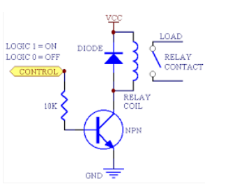
Answer
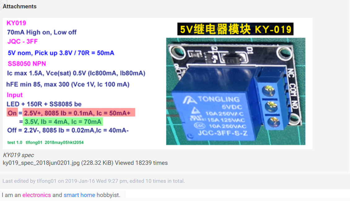
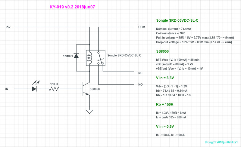
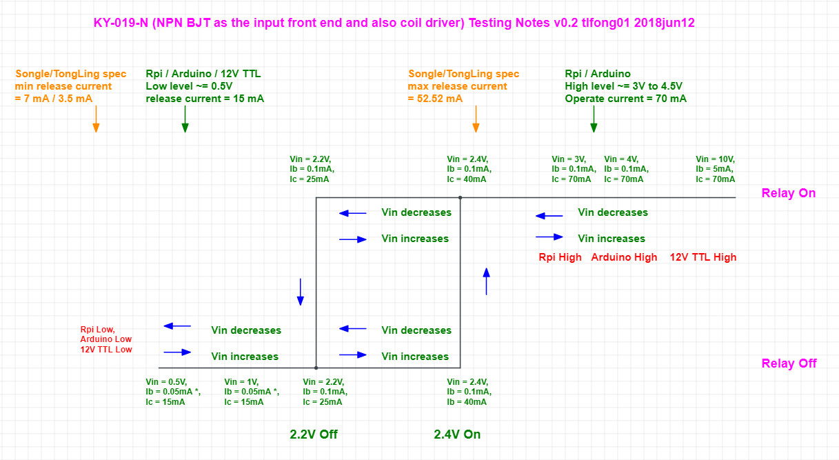
Let us study the circuit design of a real High level trigger 5V relay KY019 shown below. The relay characteristics, operation, and photo are shown in Appendices A ~ C below.
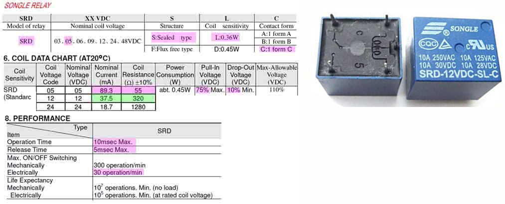
The KY019 relay uses a Songle 5V relay switch, with nominal current of 90mA (measured 70mA). GPIO High is 3V3. For the OP's 12V relay switch with smaller nominal current of 40mA, and GPIO High of 5V, it is easy to just modify the base resistor for a smaller collector current.
The NPN BJT SS8050 is used in this relay. The circuit analysis is shown in the right hand side of the schematic.
The calculation suggests a base resistance of 1kΩ. However for dirt cheap toy relays usually without any power saving requirements, the vendor usually takes a big safety margin to allow for the big variety of device parameters, a much strong base resistance 150Ω is used, to make very sure that the relays do switch, no mater how poor quality control are the transistors.
References
(1) How to properly use a relay module with JD-VCC from Arduino/Raspberry? - Asked 10 months Viewed 7k times
(2) Relay Module KY-019 5V - Rpi.org.forum 2018jun07
(3) SS8050 NPN Epitaxial Silicon Transistor - Faichild/On Semiconductor 2014nov
Appendices
Appendix A - 5V/12V/24V Relay Datasheet Summary
Appendix B - Relay switching I-V Summary
Appendix C - KY019 Relay Circuit Design Parameters
