4
\$\begingroup\$

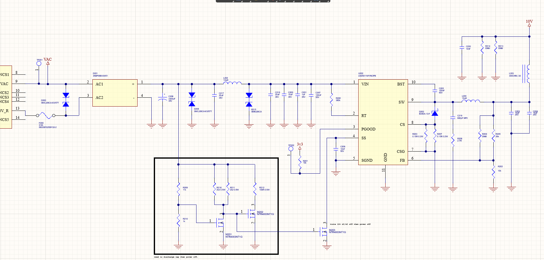
I have a power supply unit that is used to drive a couple of relays. Rarely but sometimes the input capacitors (C218, C200, C201 and C207) to the switch (U202) short when the power is turned on (230V.) Sometimes it is only one of the capacitors that is shorted (often C200,) sometimes it is all of them. We couldn't find the reason and put in a TVS (R215) after the filter in desperate move but the capacitors keep shorting. Does anyone have clue what could cause this?

Note, GND is connected to PE on this card.

  • Fs = 800kHz
  • Vin= 22V
  • Vout= 12V (not 10V)

PDF: https://www.dropbox.com/s/45owhv6dmq6l7ti/POWER.pdf?dl=0

Schematic: enter image description here


To answer some of your questions:

  • All caps between L202 and the switch are ceramic caps, the only electronytic is the bulk one after rectifier.

  • The system has been ESD-tested. Up to 4kV on the mains with no problem, the TVS's seems to deals with those spikes fine.

  • This is a rare fault on these cards. It does not happen to every card. More like 1 of 200 or something.

  • When the cards fail, the caps usually dont blow up, they look fine but are shorted. No soot or signs of stress/heat. Historically we have gotten 1 or 2 cards with blown up caps(leaving a crater in the pcb), but those are very rare. It is however that exact capacitor bank before the switch that blows up.

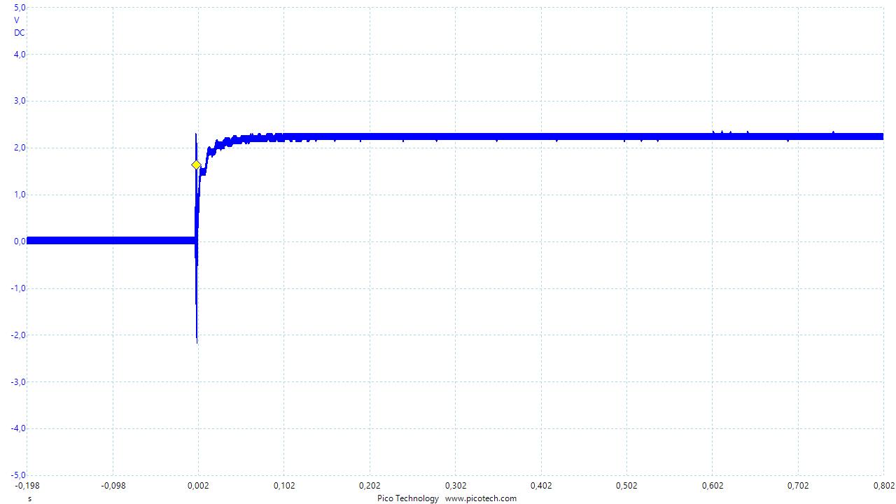
Here is a picture of the power up. Measured on VIN (U202). Voltage is 1/10 on the scale. Measured on VIN (U202).
\$\endgroup\$
21
  • 4
    \$\begingroup\$ What's the half component on the left of the picture? What's the AC voltage across pins 2/3 of D201? How does the 230 V mains get to C218? The attached png, while a lot better than nothing, is still mostly illegible at that scale, and incomplete. You're having trouble with mains switch-on killing C218? Show the entire path, legibly, from mains to C218. \$\endgroup\$
    – Neil_UK
    Commented Sep 9, 2021 at 7:47
  • 2
    \$\begingroup\$ And make your component IDs and names bigger. \$\endgroup\$
    – Andy aka
    Commented Sep 9, 2021 at 8:23
  • 2
    \$\begingroup\$ Those are huge values for ceramics, obviously very high K ceramic. I notice they're all different values, following the 'decouple all frequencies' philosophy that I find very dubious. I wonder if the LM25011 is drawing a current frequency that puts one of them into series resonance? They will all have different SRFs, and the large ones will go inductive, and a high Q resonance could kill them. With its 45 V abs max, the LM25011 may not blow as a result. You would need a 'scope to see, OR, put a 1 ohm resistor in series with each to reduce the Q as an experiment (not as a permanent fix) \$\endgroup\$
    – Neil_UK
    Commented Sep 9, 2021 at 13:04
  • 1
    \$\begingroup\$ Tagging on to @Neil_UK posit on resonance, I have found that circuits such as yours with the 12uH inductor and capacitors on the right side of the inductor will ring with current spikes. You can have ring voltages that may grossly exceed the voltage rating of your capacitors. My solution was to de-Q the inductor by placing a 10 ohm resistor across the inductor. \$\endgroup\$
    – qrk
    Commented Sep 9, 2021 at 16:51
  • 3
    \$\begingroup\$ That spike at powerup look suspect; there's clearly significant ringing. You need to inspect it at a much smaller timescale; currently you're at 100ms/div. Zoom in by a factor 10,000 or so. \$\endgroup\$
    – marcelm
    Commented Sep 10, 2021 at 14:21

3 Answers 3

4
\$\begingroup\$

Your L202 together with the switcher (U202 - LM25011) acts as a boost converter. Every time the switcher switches off, the inductor dumps its energy in the form of a high voltage spike into those capacitors, eventually destroying them. If you have an oscilloscope handy, try to capture these spikes. I am curious to see them. I would suggest to try each of these things separately:

  1. Split the 3300uF input capacitor into 2 capacitors of around 1000-2200uF, and place them on each side of the L202. Right now you have a very large cap on the input side, but much smaller caps on the other side of L202, giving you a solid/stiff DC on the left, but a significantly higher impedance on the right, incapable of sinking the spikes from L202, or sourcing the whole current to the switcher without resulting in voltage "dips" during the ON part of its cycle. You basically have voltage dips on the right side of L202 during the ON part of the switcher cycle, and voltage spikes coming from L202 during the switcher's OFF part of its cycle; you're "pumping" the L202 in a way. If the L202 only had to block smaller currents of high frequency harmonics (which I believe is its intended purpose), it wouldn't be acting this way.
  2. Remove L202 from the circuit.

P.S.: I would love to see your scope capture across those caps before and after the suggested modification, and that you let me know if it worked for you. Thank you.

\$\endgroup\$
1
\$\begingroup\$

Adding to what Dr Moishe Pippick said - the surge suppressors are rated at a dangerously high voltage - even more so than his comment suggests.

While this is nominally a 26V suppressor, it is rated at a clamp voltage of

33.2V at 1mA
42.1V at 14.2A

As others have noted, a sudden removal of load turns C217 & L302 into a boost converter. Depending on various in-component and stray capacitances & inductances voltage may well be able to exceed the 35V capacitor voltage ratings.

Changing to a SMBJ20 would allow about 32V max at 18A but is almost certainly too close to the initial breakdown voltage to be usable.

Changing to an SMBJ22 with a breakdown voltage of 24.4 V minimum may prove satisfactory and would be worth trying.

Adding a modest additional resistive load to the 22V rail (maybe lowering R209, R210 or a separate resistor) would help reduce peak Voc. An input clamp zener dissipating minimal wattage at 22V but very usefully more at slightly above that may be a useful complement to the surge protectors.

Even an SMBJ24 provides very useful clamping at 35V and is rated at Vrwm_min of 24 volts and Vbr of 26.7V.

enter image description here

\$\endgroup\$
1
  • 1
    \$\begingroup\$ That's what I have realized about TVS components; their voltage range is very wide. For most of my purposes, I have found that zener diodes rated for at least 1W act sufficiently well, and have significantly narrower active voltage range. At less than 1W, zeners don't respond fast enough, they just don't cut the peaks off, probably because they can't absorb enough current. \$\endgroup\$ Commented Sep 14, 2021 at 9:18
0
\$\begingroup\$

The SMBJ26CA transient suppression diodes have a nominal 26 V rating, but the peak is shown as 33.2 V, perilously close to the 35 volt rating of the capacitors. Use caps with higher voltage rating. At ~US$4 per cap, they're a bit pricey to blow out frequently.

\$\endgroup\$
2
  • 3
    \$\begingroup\$ They are in parallel with the 3300uF cap that is shown as polarized so I suspect the schematic is correct and those 22uF and 10uF caps are ceramics. \$\endgroup\$ Commented Sep 10, 2021 at 1:49
  • \$\begingroup\$ @KevinWhite, Sorry, I had not known 22 µF caps existed! Mouser does carry them, and I'll amend the answer. \$\endgroup\$ Commented Sep 10, 2021 at 19:04

Your Answer

By clicking “Post Your Answer”, you agree to our terms of service and acknowledge you have read our privacy policy.

Not the answer you're looking for? Browse other questions tagged or ask your own question.