3
\$\begingroup\$

I lately built a 10W amplifier using a TDA2003. I used this circuit (though I removed R4 since I didn't have it, C4 is 50n (two 100n's in series) and R1 is 50Ohm (two 100Ohm's parallel)):
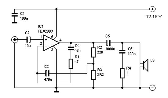
enter image description here

Everything worked fine and there was no noise as far as I could hear.

Now, I wanted to be able to switch between two inputs, like this:
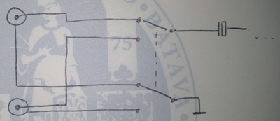
enter image description here

This works, but I get a lot of noise now. All wires are shielded, so I concluded the noise arises in the switch and is amplified after that. Is this correct or am I jumping to conclusions?

How can I decrease the noise? I do not want to switch later, after the amplification, that would produce too much heat and consume too much energy since I'd have to amplify two signals of which I'd only use one.

\$\endgroup\$
10
  • \$\begingroup\$ Where did you get 50 ohm resistor and 50 farad capacitor? \$\endgroup\$
    – AndrejaKo
    Commented Feb 22, 2013 at 11:32
  • 1
    \$\begingroup\$ Combined from two 100Ohm resistors and two 100n capacitors (not 50 farad, 50 nanofarad) (I edited my question to add this information) \$\endgroup\$
    – user17592
    Commented Feb 22, 2013 at 11:33
  • 3
    \$\begingroup\$ For one thing, you don't need to switch the ground leads on the input connectors; just tie them all together. Can you describe the noise? Is it just a click when switching, random crackling and/or hiss, or hum? \$\endgroup\$
    – Dave Tweed
    Commented Feb 22, 2013 at 12:33
  • 1
    \$\begingroup\$ @Camil Staps I thing that the best idea would be to actually figure out what was happening. Just "link grounds together" doesn't explain the underlying problem, although it does provide hints. As for the "clean" part, I meant if there are any sources of electrical noise such as switch-mode power supplies, inverters, powerful CCFLs or similar that could emit electrical fields which could be picked up by switch assembly. \$\endgroup\$
    – AndrejaKo
    Commented Feb 22, 2013 at 13:59
  • 1
    \$\begingroup\$ Right, so the hint would be that the inactive signal becomes noise because the ground isn't grounded? For the rest, I do have a clean environment, yes, thanks for the explanation. \$\endgroup\$
    – user17592
    Commented Feb 22, 2013 at 15:12

1 Answer 1

1
\$\begingroup\$

In order to debug and try and solve this I'd suggest the following (requires oscilloscope):

1)Use an oscilloscope with FFT capability on the output. Then you can tell what is the spectrum of the interference. In fact in Audio system testing, this is done with automated equipment to ensure a high SNR. If the noise is rather narrow, then it's likely something is oscillating and that's easier to fix than if it is wideband.

2) Connect an oscilloscope to VCC and take a look. Do you see anything out of the ordinary like waves riding on it? If you do, an LDO or regulator can act as a low pass filter and filter a lot of noise out of it. Might be a good idea to use a clean supply as well.

\$\endgroup\$
1
  • \$\begingroup\$ I guess that would have solved the issue as well, so I accepted it. Thanks! \$\endgroup\$
    – user17592
    Commented Feb 22, 2013 at 16:01

Your Answer

By clicking “Post Your Answer”, you agree to our terms of service and acknowledge you have read our privacy policy.