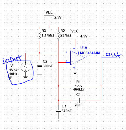
I have stumbled upon the below circuit. I can't understand why there is a capacitor in the positive and negative inputs. Can anyone please explain to me the purpose of the capacitor in this circuit and this circuit how work ?

-
2\$\begingroup\$ It looks it is meant to stabilize the input and output bias at about mid Vcc. Notice Vee is different than Vcc which is also terrible labeling equivalent to having two positive supplies and naming one "positive" and the other "negative". Seriously, why? \$\endgroup\$– DKNguyenCommented Sep 29, 2021 at 13:28
-
5\$\begingroup\$ Where exactly did this stumbling occur (source of your image) and what is the circuit supposed to do? \$\endgroup\$– Spehro 'speff' PefhanyCommented Sep 29, 2021 at 14:17
-
1\$\begingroup\$ C2 and R3 don't do anything at all and C3 likely causes an oscillation at umpteen MHz. If V1 were AC-coupled then R3/C2 would make sense, biasing the opamp + input to mid rail, resulting in a non-inverting gain of 3 with a one-pole low pass at 17Hz. But C3 is problematic: its impedance goes to zero at high frequencies so the opamp gain explodes at those frequencies. \$\endgroup\$– td127Commented Sep 29, 2021 at 17:23
1 Answer
In your circuit, that capacitor C2 does nothing.
Why?
Because it is in parallel with the voltage source V1.
So the voltage across the capacitor C2 will be the voltage set by V1.
All the current that flows into and out of the capacitor C2 will be supplied / absorbed by V1.
The other components in this circuit cannot "see" the influence of this capacitor as they are only connected to the capacitor through the net called "input" which has a voltage determined by... yes, V1.
The presence of C2 will only make sense if there is some resistance/impedance in series with V1. Then that series resistance and C2 form a simple low pass filter.
This isn't a very well designed circuit. For example there is a capacitance from the output of the opamp directly to ground (C1 in series with C3). Many opamps don't like this at all. Improve the design by adding a series resistor in series with C3 or C1 (or both).
