0
\$\begingroup\$

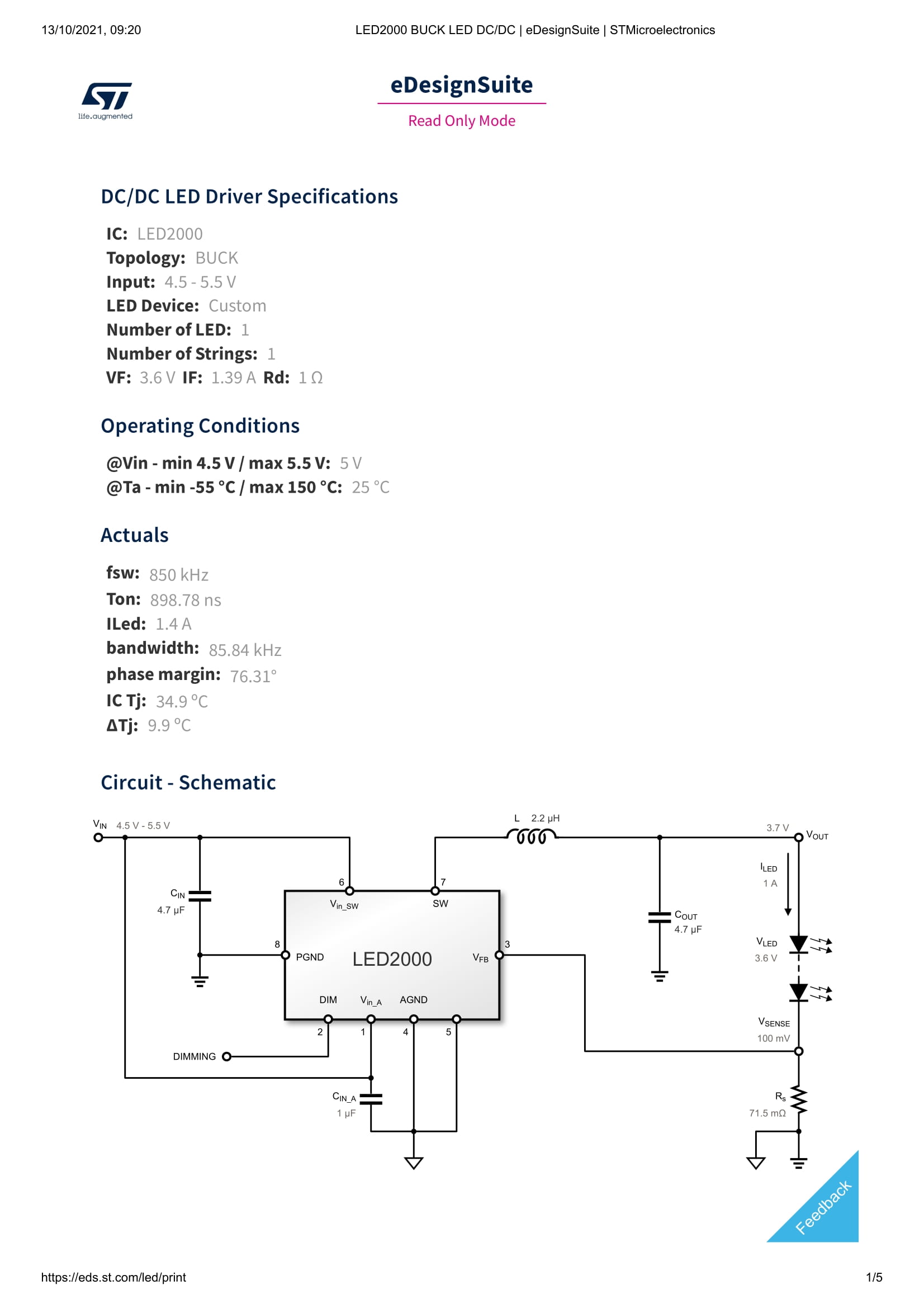
I'm designing a buck LED circuit using a LED2000PUR (Data sheet). The issue that I am having is that the LED I'm designing for doesn't have a data sheet, and I need to determine the dynamic resistance so that I can select an appropriate output capacitor. The only parameters that I know, is the LED runs off of 3.6 V and has an If of 1.39 A.

Here is the link for what I am designing for.

Information about dynamic resistance can be found on page 15 and information about inductor and output capacitor selection can be found on page 22 of the datasheet.

My system will run off of 5 V from a powerbank.

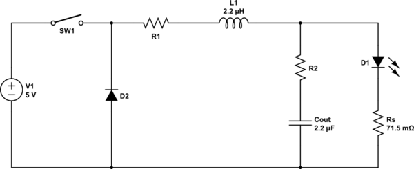
Below is an equivalent circuit:
schematic

simulate this circuit – Schematic created using CircuitLab

The manufacturer has a tool on their website where entering the input voltages and LED specifications will output recommended components. I've preferred this as I'm not an Electrical Engineer and I find the data sheet to be oddly written.

My observations from manipulating the values are:

  • Cout capacity and voltage decrease when Rd increases
  • Cout values decrease when LED ripple percentage increases
  • Cout values decrease and L values increase when Il Ripple percentage increases

Schematic LED2000

\$\endgroup\$
17
  • \$\begingroup\$ Unless that's a UV LED , it's an odd looking LED Vf, If, but typically at 5W it has an Rd ~ 1/2Pd or 100 mOhms. Show LED P/N & link in Q. \$\endgroup\$
    – D.A.S.
    Commented Oct 12, 2021 at 23:15
  • \$\begingroup\$ The datasheet contains a method for determining the LED dynamic resistance at the operating point. Have you tried that method? \$\endgroup\$
    – Justme
    Commented Oct 12, 2021 at 23:16
  • \$\begingroup\$ @TonyStewartEE75 How so? White LEDs can have Vf from 3 to 5. The LED is from an AliExpress seller. It's packaged with a lens, and I've asked the seller for data sheets and information about it, but they have just provided me wattage and other optical characteristics like lux etc. \$\endgroup\$
    – MechFlag
    Commented Oct 12, 2021 at 23:44
  • \$\begingroup\$ Save yourself some trouble, no datasheet, no sale. \$\endgroup\$
    – Tyler
    Commented Oct 12, 2021 at 23:47
  • \$\begingroup\$ @Justme the data sheet says “If the LED data sheet does not report the equivalent resistor value, it can be simply derived as the tangent to the diode I-V characteristic in the present working point” I don't have a I-V characteristic graph. But if I'm understanding correctly, the Rd value can be determined from I/V, so 1.4/3.6 = 0.39 ohms \$\endgroup\$
    – MechFlag
    Commented Oct 12, 2021 at 23:48

1 Answer 1

2
\$\begingroup\$

Measure the dynamic resistance as per the instructions in the datasheet.

Plot a I-V curve of your LED around the bias point and draw a tangent at the bias point to have a line with dV/dI.

Then you can calculate a value for the capacitor.

\$\endgroup\$
3
  • \$\begingroup\$ This might be a basic question, but it is lost on me. After finding the bias point to be 2.57 ohms, how can I plot a I-V curve if I have no other information about the LED except for its voltage and forward current? \$\endgroup\$
    – MechFlag
    Commented Oct 13, 2021 at 2:59
  • \$\begingroup\$ Your assumption is wrong for 2.57 Ohms for a VI=P= 4 W LED , @MechFlag that would be the linear R equivalent, not the exponential LED slope \$\endgroup\$
    – D.A.S.
    Commented Oct 13, 2021 at 5:28
  • \$\begingroup\$ @MechFlag You need to do the plot by measuring LED current and voltage at different bias points yourself. For example use a lab power supply and adjust the the current slightly up and down and see the change in voltage. Or adjust the voltage slightly up and down to see change in current. \$\endgroup\$
    – Justme
    Commented Oct 13, 2021 at 6:55

Your Answer

By clicking “Post Your Answer”, you agree to our terms of service and acknowledge you have read our privacy policy.

Not the answer you're looking for? Browse other questions tagged or ask your own question.