ESP-PSRAM64 uses a bidirectional QuadSPI interface at up to 133MHz. I am connecting this to an STM32 microcontroller. Normally I would use some series termination resistors at the source (e.g. for a high speed image sensor) but as it is bidirectional, both ends play the role of source at one time or other.
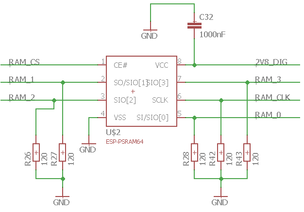
I am at the schematic stage so haven't yet tested hardware. Instead of series resistors, I have placed termination resistors (120R) between each data line (SIO0 - SIO3) and ground as well as between the clock line (SCLK) and ground. In layout I have placed these at the ESP-PSRAM64 end as there is more space there and it feels as valid as putting them at the STM32 end. I also expect the pin capacitance of the STM32 to be higher than that of the ESP-PSRAM64 making the ESP-PSRAM64 the better end to have these resistors at.
Schematic extract at the RAM end:

Am I correct in thinking that these will work very well when the STM32 is sending data to the ESP-PSRAM64 and moderately well when the ESP-PSRAM64 is playing the role of source. In the latter case, I'm expecting it to be as good as series termination resistors as then won't stop the first reflection but will the second.
In reality the traces are short (about 40mm) so it's probably not too critical. I haven't length matched as the frequency isn't particularly high and they'll match to within about 8mm (~3ps or 1/300 clock periods).
Suggestions welcome please. How would you improve on this proposal? I haven't seen any schematics online of designs successfully using this part (ESP-PSRAM64). The closest I can find is SD card circuits, but they often need pullups to function.
