2
\$\begingroup\$

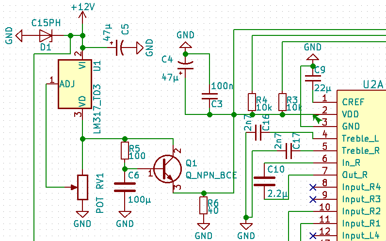
The ERC on my schematic keeps on failing due to a Type 3 error (VDD pin of an IC not driven) despite the fact that it does receive power via a voltage regulator and an NPN transistor. See the schematic attached:

ERC error on IC pin #2

Pin #2 is configuread as a +9 V power input. The current flows from the +12 V source in the upper left corner (which is attached to a power flag and input connector) through the DC regulator (U1) and the transistor (which runs a capacity multiplier following an advice I received in this forum; Q1; type BC547C) to the IC (U2A).

Nevertheless, this construction fails in the ERC:

ErrType(3): Pin connected to some others pins but no pin to drive it @ (80.01 mm, 38.10 mm): Cmp #U2, Pin 2 (power_in) not driven (Net 50).

Why not? Is this because of the transistor, whose emitter is not regarded as a power output?

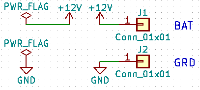
UPDATE: I do use power flags. See this screenshot:

Power flags

A look into the library editor revealed that the C and E connectors of Q1 are configured as "passive". May this be the culprit?

\$\endgroup\$

2 Answers 2

5
\$\begingroup\$

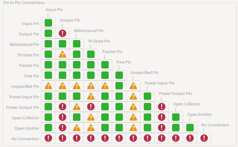
Kicad has no idea of your intended usage nor where power comes from. It has ERC rules that check common issues and checking that power-in is driven from something that can provide power is one such use-case.

enter image description here

Some parts have a Power-Out but most of the time you must inform Kicad where the power comes from

You need to add a PWR_FLAG symbol to inform Kicad what nets are capable of providing power

enter image description here

https://docs.kicad.org/master/en/getting_started_in_kicad/getting_started_in_kicad.html#43

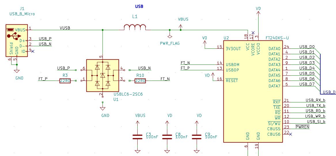
Such power flags MUST be on all nets that provide power. It isn't enough to place on the global power flags (+5, +3v3) as sometimes ferrites are used and kicad does not know the intent of a circuit.

enter image description here

Looking at the picture from the OP, U2A.2 (Vdd) is connected to Q1.3 and thus this could be the source of this additional power rail, or is it via the top trace that is going off-screen.

Nets that provide power must be marked as such

\$\endgroup\$
5
  • \$\begingroup\$ I have already done that. Otherwise I would have received a bonanza of errors. \$\endgroup\$
    – Neppomuk
    Commented Nov 28, 2021 at 15:28
  • \$\begingroup\$ have you done it everywhere? Q1 looks like it is providing the power to U2 and that net does not have a power flag \$\endgroup\$
    – user16222
    Commented Nov 28, 2021 at 15:36
  • \$\begingroup\$ Q1 can't have a power flag, as it receives power from pin #3 of U1, so that it only forwards power. \$\endgroup\$
    – Neppomuk
    Commented Nov 28, 2021 at 15:41
  • \$\begingroup\$ Q1 emitter can have a power flag. Kicad needs to be informed where power comes from and power will flow through Q1. \$\endgroup\$
    – user16222
    Commented Nov 28, 2021 at 15:41
  • \$\begingroup\$ Aaahhh, now I do understand what you mean! I should attach a power flag to the line right behind the emitter, right? Nevertheless, I've found a more elegant solution. See my answer below. \$\endgroup\$
    – Neppomuk
    Commented Nov 28, 2021 at 16:05
0
\$\begingroup\$

OK, I've found the culprit: In an NPN transistor, collectors and emitters are marked passive! This is why Kicad seems to recognise a break in the power line.

Solution: I created a new component from Q_NPN_BCE, named it BC547C (at least this is the transistor type they sold me), and marked the collector as power input and the emitter as power output (so that the transistor practically becomes a power regulator). Now everything works fine, and my net passes the ERC. :)

\$\endgroup\$
3
  • 4
    \$\begingroup\$ This is NOT the right way todo it. the pins of the BJT are meant to be passive. Just because your usage is implying powerflow does not mean all usage are. If you do this you will cause other problems \$\endgroup\$
    – user16222
    Commented Nov 28, 2021 at 16:31
  • \$\begingroup\$ I did it for this specific type of transistor only. I saved it as a power transistor under its part name in my parts lib instead of overwriting the original part. \$\endgroup\$
    – Neppomuk
    Commented Nov 28, 2021 at 16:59
  • 3
    \$\begingroup\$ Right. So the next time you pull that out of your library to use it as something else, the ERC will be all screwed up. This is probably not as much of an error if you're the only one to ever use those design files, but as soon as someone else uses your library, it'll cause problems. It's one of those situations where there's no one truly elegant solution, so you try to do what's going to be least confusing to folks down the road. \$\endgroup\$
    – TimWescott
    Commented Nov 28, 2021 at 17:51

Your Answer

By clicking “Post Your Answer”, you agree to our terms of service and acknowledge you have read our privacy policy.

Not the answer you're looking for? Browse other questions tagged or ask your own question.