In a previous answer I offered a method for calculating a quantitative result for what a voltmeter will read when a time-varying magnetic field may be affecting the circuit and/or leads of the voltmeter.
A voltmeter measures the (negative of the) total emf around any loop of which it is a part, minus the voltage drop on any element in that loop that drops voltage [besides the voltmeter itself].
If a voltmeter, together with its test leads, is connected to test points A and B in a circuit, it forms a path. This path, together with any path between A and B within the circuit, forms a closed loop... If we know the emf of that loop and all the voltage drops except that of the volt-meter, then we can calculate the voltage drop through the volt-meter. That is what the volt-meter measures. The voltmeter will display the emf of the loop minus the voltage drops of all the path segments other than the voltmeter.
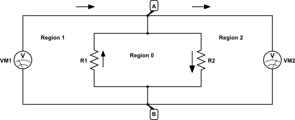
Let me give a concrete example. Suppose we have the circuit below:

simulate this circuit – Schematic created using CircuitLab
nd further suppose that there is a time varying magnetic field in Region 0, but no time varying magnetic fields in Regions 1 & 2.
There are multiple loops that include VM1 and the test points A and B. Our method says that it doesn't matter which loop we choose. Let's first choose the loop that encloses only region 1. Since there is no time-varying magnetic field in region 1, there is no emf induced in the loop enclosing it. So, our method says that the voltage reading in VM1 should be equal to the voltage drop across R1.
We can calculate the voltage drop across R1 if we know the values of R1, R2 and the rate of change of magnetic flux in Region 0. The rate of change of magnetic flux in region 0 will give us the emf in the loop enclosing Region 0. Let's call that \$\mathscr{E}_0\$. Assuming the voltmeters draw no current, the current through R1 and R2 will be
$$ I_0 = \frac{\mathscr{E}_0}{R_1+R_2} = I_{R_1} = I_{R_2}$$
So the voltage drop across the components in the loop other than the voltmeter is just the negative of the voltage drop across R1 (directional arrows in diagram oppose), or \$-I_{R_1}R_1 = -I_0R_1\;\;\$ , so the VM1 voltmeter reading will be
$$VM1Reading = 0 - (-I_0R_1) = I_0R_1$$
Now, our method says that it doesn't matter which loop we choose as long as it includes the voltmeter and it's leads. So, let's try another loop. This time, the loop that includes both Region 1 and Region 0.
Since we have assumed that the only region with a time-varying magnetic field is Region 0, the emf around the loop enclosing Region 1 and Region 0 is equal to the the emf around the loop enclosing Region 0, which we have already calculated as \$\mathscr{E}_0\$. The voltage drop across the components other than the voltmeter is the voltage drop across R2 this time, which is \$I_0R_2\$ . So using the loop around Regions 1 and 0, we get
$$VM1Reading = \mathscr{E}_0 - I_0R_2 $$
However, as promised, these two answers have the same value.
$$I_0R_1 = \frac{\mathscr{E}_0}{R_1+R_2}R_1 = \frac{\mathscr{E}_0(R_1 + R_2 - R_2)}{R_1+R_2}= \mathscr{E}_0 - I_0R_2 $$
Now let us consider what will VM2 will display. We can choose either the loop which encloses Region 2 alone, or the loop that encloses both Region 0 and Region 2. Let us choose the loop that encloses both regions. By our assumptions, the time varying magnetic field that is enclosed by both regions is the same as that enclosed by Region 0. So, the emf around that loop is just \$\mathscr{E}_0\$. However, the for the voltmeter VM2 is pointing in the opposite direction, so we will need to account for that. The resistive voltage drop in that loop is just the resistive voltage drop across R1. So, the voltage reported by VM2 is
$$-\mathscr{E}_0 + I_0R_1$$
[It may be surprising to some the voltmeters VM1 and VM2 will display different values even though both are connected to the test points A and B. However, this is consistent both with theory and experiment.]
Now, I believe that this method of calculating what a voltmeter will report when a time-varying magnetic field is affecting a circuit (and possibly the voltmeter leads) gives the correct value, while others seem to disagree.
My question is Is this a mathematically valid way to determine quantitatively what a voltmeter will report when a time-varying magnetic field is affecting a circuit and/or the leads of the voltmeter?
I am not looking for answers that argue about the validity or otherwise of KVL or make other arguments, unless such arguments support an answer one way or the other about whether this method gives valid results or not.
