2
\$\begingroup\$

I have a circuit with a SuperCap used as a battery. I want to know the curve of SC voltage in time to finnaly measure its self-discharge.

Is this can be done with a simple arduino or another microcontroller throught the ADC if I programm the ADC with interrupts every hours for example ?

The idea is to avoid to the maximum the leakage current in the ADC, to perform a reliable measure in time. I found that ADC on the arduino as a Impedance of approximatly 6 MOhms, does this permit the measure I want ? There will be of course a voltage drop in the arduino.

The other option is to seperate the measure points and the SC with a relay commanded by the arduino when it has to make a measure.

The process will act the act with the followings steps :

  • Wait for interrupt, Relay = open: no measures

  • Time interrupt (every hour), closing the relay

  • Read the SC Voltage,

  • End of interrupt, opening the relay

  • Wait for interrupt

What do you think about this second method ?

\$\endgroup\$

4 Answers 4

1
\$\begingroup\$

One important thing you didn't mention is whether the voltage you are measuring is already within the A/D range, or if it needs to be attenuated before being presented to the A/D.

If no attenuation is needed, then just connect the cap directly to the A/D input. Make sure there isn't anything else connected to that input. The leakage current of the A/D input is then your discharge current error. You have to look it up, or course, and compare that to the expected discharge current. Most likely, the A/D leakage current is much smaller than what you are trying to measure.

If attenuation is needed, then you could buffer the cap signal with a opamp that has high input impedance, then attenuate the output of that. Or, you can use a P channel FET with sufficiently low off-state leakage to connect the cap to the attenuator. This would only need to be done for a few µs every sample, which could be every minute or so. The average current thru the attenuator is then so small as to be irrelevant.

\$\endgroup\$
2
  • \$\begingroup\$ Thank you about that. I dont neeed a voltage attenuation indeed. Do you have any idea of the leakage current throught an A/D ? \$\endgroup\$
    – Marech
    Commented Aug 30, 2018 at 14:33
  • \$\begingroup\$ @Mar: No, but the manufacturer certainly does, and has surely given you that information in the datasheet. \$\endgroup\$ Commented Aug 30, 2018 at 14:39
0
\$\begingroup\$

Welcome to SO!

I would just measure the voltage straight on the ADC if possible.

The ADC of the Arduino looks something like this. The impedance that you mention is not a permanent resistor that will pull current. All that happens is that a tiny capacitor (e.g. 14pF) charges up every time you measure the current. The amount of current that this will pull is very small. You could even calculate this current with a calculator like this.

The reason why you might need an opamp is if the SC's voltage is higher than the ADC's max value, of which the chances are good. In that case I would use a pico bias opamp like @Scott mentioned, but only to step down the voltage.

@Olin has given a good explanation of what I'm trying to convey.

\$\endgroup\$
0
\$\begingroup\$

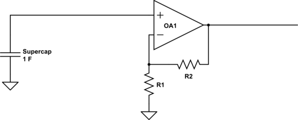
What about this:

schematic

simulate this circuit – Schematic created using CircuitLab

Why would this be better? Because if you use a JFET or CMOS Opamp, the bias current is in pico amps. LMP7721 for example has 3fA , yes femto amps not even pico nor nano.

\$\endgroup\$
4
  • 1
    \$\begingroup\$ You should probably describe WHY you recommend this, and what type of op amp should be used. Also, bias current might be an issue (though likely small compared to what the OP suggests) \$\endgroup\$ Commented Aug 30, 2018 at 14:15
  • \$\begingroup\$ This could work but the problem would be the same as my supercap is already on the board. The two grounds you represented would be connected then. What about the bias current in the op amp now ? \$\endgroup\$
    – Marech
    Commented Aug 30, 2018 at 14:18
  • \$\begingroup\$ The current drops in my board is theorically valued as 700nA. If the bias current of the op amp is 100nA I get an huge leakage no ? \$\endgroup\$
    – Marech
    Commented Aug 30, 2018 at 14:24
  • \$\begingroup\$ @Marech there are op amps with bias in picoamps. \$\endgroup\$ Commented Aug 30, 2018 at 14:27
0
\$\begingroup\$

Input current on an analog input is 1 microAmp max. 0.000001 A. Small enough that a hand waving nearby can be picked up. You would use more total current x time with 10-15mA to energize the relay and let it finish bouncing to make a measurement periodically

\$\endgroup\$
2
  • \$\begingroup\$ 1 microAmp is the current while measuring right ? It's approximatly what I have as a leakage current in my board. This current is acceptable if the measure takes a few microseconds but the port ADC pin needs to be "opened" after right ? I dunno if its possible on every micorcontroller. \$\endgroup\$
    – Marech
    Commented Aug 30, 2018 at 15:01
  • \$\begingroup\$ Atmel Atmega328P and similar 8-bit parts, yes. ADC mux disconnects from the sample and hold capacitor when not making a measurement. \$\endgroup\$
    – CrossRoads
    Commented Aug 30, 2018 at 15:16

Your Answer

By clicking “Post Your Answer”, you agree to our terms of service and acknowledge you have read our privacy policy.

Not the answer you're looking for? Browse other questions tagged or ask your own question.