5
\$\begingroup\$

I am designing an audio amplifier circuit which consists of an I2S digital MEMS mic (INMP441) for picking up voice signals and an I2S class-D amplifier (MAX98357A) for amplification.

Both these ICs have three lines (Serial Data, Serial Clock, Word Select) for I2S communication.

I have a doubt: can we tie these communication pins of both ICs to each other without of a use of microcontroller? I want to know whether this combination would work or not. I have attached a rough block diagram below.

Would you guys please check whether this combination will work or not?

enter image description here

\$\endgroup\$
1
  • \$\begingroup\$ Look at the I2S timing diagrams and timing tables in the respective data sheets to find this out. \$\endgroup\$
    – Andy aka
    Commented Jan 13, 2022 at 11:48

3 Answers 3

13
\$\begingroup\$

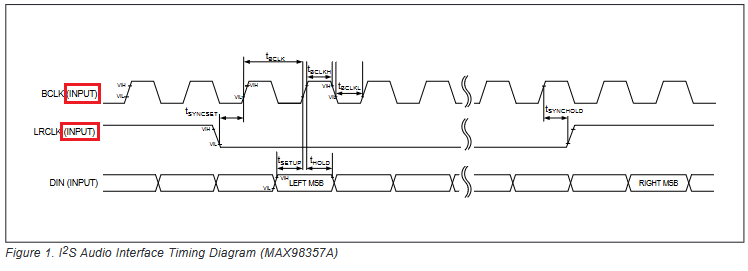
No, this won't work. Both devices are I2S slaves. That means BCLK and LRCLK are inputs on both ICs.


enter image description here


enter image description here


You'll need something in the middle to bridge the two. This boils down to generating BCLK and LRCLK at the appropriate rate (and voltage levels) and supplying them to both ICs. Depending on the application and your skill set, the easiest way to do this might be with an MCU, but in principle you could also do this with an oscillator (running at a rate of fS * 64 to generate BCLK) and a 6+-bit counter IC to generate a divided LRCLK. (Note that the MAX98357x supports BCLK at 32x, 48x or 64x LRCLK [p. 6], but the INMP441 only supports 64x [p. 11]).

\$\endgroup\$
2
  • 1
    \$\begingroup\$ Any microcontroller with a timer peripheral (so basically, any) can generate these clocks. No I2S interface required on the MCU. \$\endgroup\$
    – Ben Voigt
    Commented Jan 13, 2022 at 23:26
  • \$\begingroup\$ @BenVoigt Good point, edited. Thanks. \$\endgroup\$
    – TypeIA
    Commented Jan 14, 2022 at 0:57
9
\$\begingroup\$

Unfortunately, no. At least, not that way. The BCLK (or SCK) and LRCK (or WS) are inputs on both of these devices (they are both I2S slaves). On the schematic you shown, there is no device driving those signals. It could not work without at least a proper I2S clock generator. You need a clock that drives LRCK at the sample rate you want, and BCLK at 64 times the sample rate you want.

However, you could do this without a microcontroller: grab an oscillator running at 64x the sample rate to drive BCLK (there are off-the-shelves oscillators for this), and a frequency divider that divide this clock by 64 (you could simply use a 6 - or more - bits counter: e.g. 74HC393) to drive LRCK. A microcontroller is actually overkill to generate such a simple clocking scheme.

Anyway, now it can start working. There are a few things to take care of, though:

  • INMP441 works in I2S mode only (MSB first, with a 1clk delay between the MSB of each word and the LRCLK transition), with a 32 bit word length. It can output its stream on the left or rigth channel depending on the L/R input, but that's pretty much all you can configure. It will drive the data out line for the L or R word part depending on its configuration, but the data line isn't driven for the remaining part (so you can wire two mics on the same lines to make it stereo). Therefore, you need a pull down on the data line.
  • MAX98357x works in a number of modes (left-justified, I2S, TDM). You want I2S. The choice between TDM and the other modes is automatic because in TDM, there is just one pulse on the LRCK line and the chip detects it. The chip won't select this mode, which is fine. Now, the choice between I2S and left-justified depends on the chip variant: MAX98357A/MAX98357B. You want the MAX98357A.
  • MAX98357A will aceept 32 bits word length. Fine.
  • MAX98357A will take either the left channel or the right channel as input depending on the SD_MODE pin configuration (table 5). Make it consistent with what you decided for the INMP441 L/R configuration.
  • INMP441 seem to support any sampling frequency between ~7.8khz and 50kHz (datasheet says SCK should be between 0.5MHz and 3.2MHz). MAX98357A supports only 8kHz, 16kHz, 32kHz, 44.1kHz, 48kHz, 88.2kHz and 96kHz sampling frequencies. Choose something that fits.
\$\endgroup\$
3
  • \$\begingroup\$ Thank you for your comment. If you have any application notes that tells about, how to use oscillators and frequency divider for this type of application would be really helpful for beginners like me \$\endgroup\$
    – Sri
    Commented Jan 31, 2022 at 8:09
  • \$\begingroup\$ @Sri I tried to find app notes on this, but couldn't find any. There are posts on various forums talking about this solution, but they don't go in more details than what I wrote above. If you're at a loss, you can always ask another question, like: "How do I generate the required I2S clock signals to make those two slaves communicate?". \$\endgroup\$
    – dim
    Commented Jan 31, 2022 at 8:44
  • 1
    \$\begingroup\$ @Sri - Hi, Now that you have asked the follow-up question suggested in the above comment, I recommend that you upvote all useful answers (if you didn't do that already) and accept the most useful answer in order to effectively close this question. It causes confusion if you have multiple "open" questions on the same topic, hence why your next question should clearly be indicated as a subsequent, follow-up question, to avoid it being seen as a duplicate, parallel question. Thanks. \$\endgroup\$
    – SamGibson
    Commented Jan 31, 2022 at 12:49
1
\$\begingroup\$

If you want to this type of interface between a digital microphone and a class-D (or any other type) amplifier then you need a different digital comms interface altogether. You may want to consider something like a MAX98358 PDM Input Class D Stereo Audio Power Amplifier (or anything similar with PDM input), and hook it up to two PDM output digital microphones with buil-in pre-amplifier (a suitable clock source is required common to both devices). There may be mono options to consider, but essentially it's a PDM output mic to a PDM input amp - no microcontroller to get in the way. Check out the FAN3852 digital mic pre-amps with PDM outputs or similar. good luck !

\$\endgroup\$

Your Answer

By clicking “Post Your Answer”, you agree to our terms of service and acknowledge you have read our privacy policy.

Not the answer you're looking for? Browse other questions tagged or ask your own question.