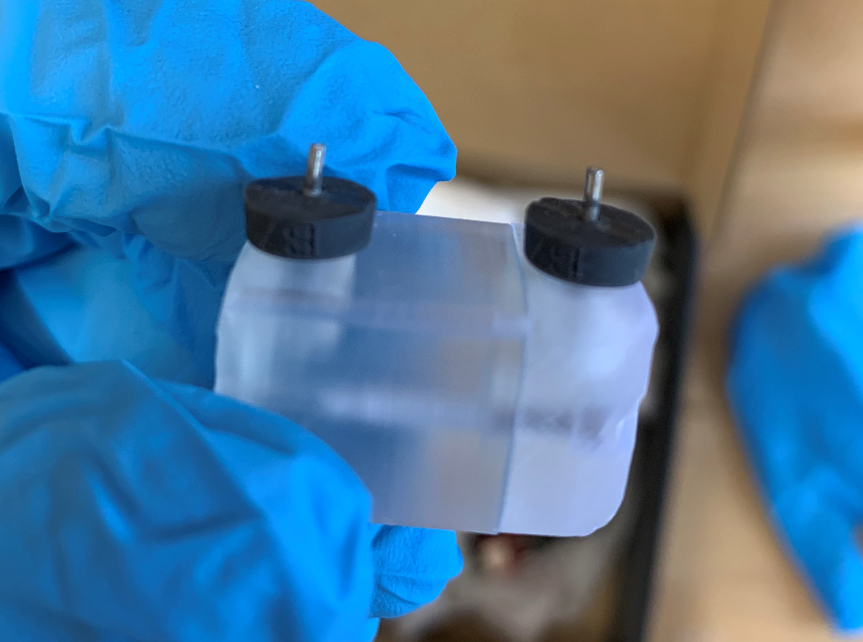
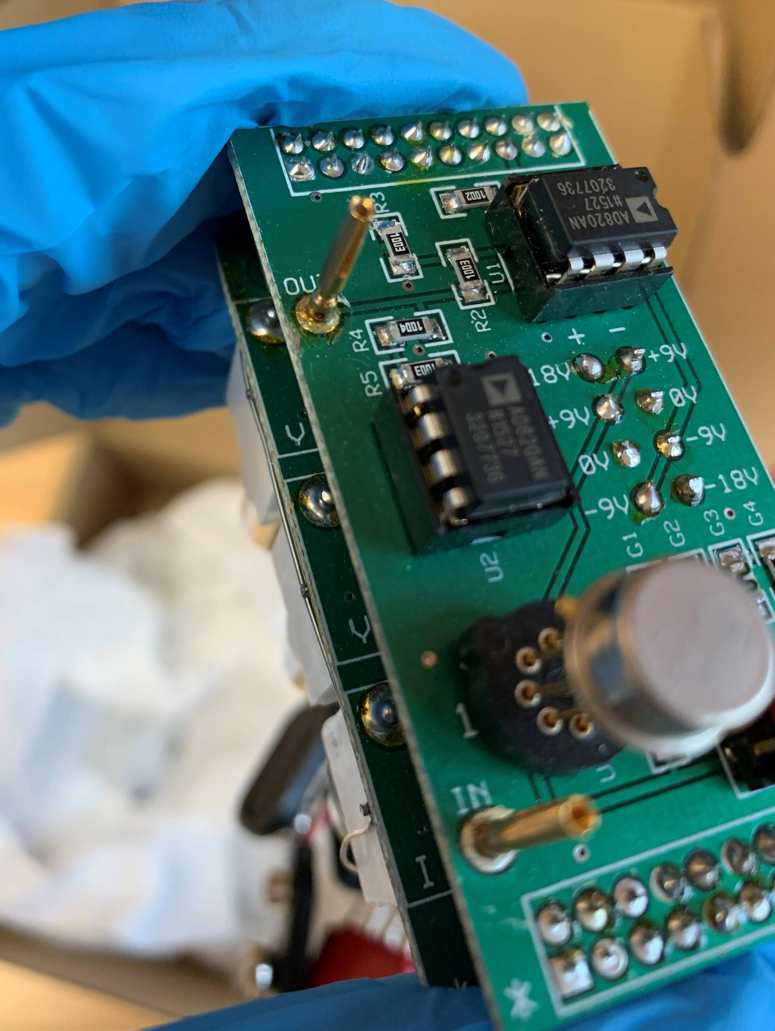
As the title suggests, I need to connect silver electrode wires that are about 1 inch long and 1mm diameter (sticking rigidly out of a microfluidic cell) to a transimpedance amplifier. The problem is that the current coming from the electrodes will be at the pico/nano ampere scale. The transimpedance has gold connector slots for the current from the electrodes. Sorry for the poor quality images. Any suggestions are greatly appreciated! Thanks!


-
3\$\begingroup\$ You're asking about pins sticking out of a cell, and terminal screws on a DAQ, yet show images of PP3 battery connectors, and BNC sockets on a DAQ. You can solder to silver pins/wires. You need BNC plugs to connect to BNC sockets. You can get wire to BNC adpaters. My favourite is to buy a BNC to BNC lead, cut it in half, and then you have two wires-to-BNC leads! \$\endgroup\$– Neil_UKCommented Feb 15, 2022 at 9:13
-
\$\begingroup\$ Long leads are a bad idea for transimpedance amplifiers, so make a small PCB with the amp and solder the wires to the amp as close as you possibly can. The output can be a normal 50 ohm cable which plugs into whatever you want. \$\endgroup\$– user1850479Commented Feb 15, 2022 at 20:18
-
\$\begingroup\$ @Neil_UK I have updated my question and the images after reading the comments and realizing I was looking at the set-up wrong. \$\endgroup\$– Gerald WilsonCommented Feb 20, 2022 at 1:04
-
\$\begingroup\$ @user1850479 Thank you for your input! I have updated my question and the images. Let me know if it makes more sense now. \$\endgroup\$– Gerald WilsonCommented Feb 20, 2022 at 1:05
-
1\$\begingroup\$ Perhaps silly question: do the board and cell line up? Can you just shove one onto the other? \$\endgroup\$– DKNguyenCommented Feb 20, 2022 at 1:27
1 Answer
Edit:
I think I understand the problem better now, but more information is needed.
- We have the electrodes in the microfluidic cell.
- We have a transimpedance amplifier
- We have terminal screws on a DAQ
A transimpedance amplifier converts current to voltage and then amplifies that voltage by an amount determined by a resistor.
So, for instance, if you convert a few picoamperes into a few picovolts we can then amplify that (through one or more opamps) to a few volts that we know will have a certain drop because of the resistances we measure in the wire and connectors. With some very careful measuring and very high quality parts, a transimpedance amplifier on the electrodes side could be built.
However, if the transimpedance amplifier is already expecting certain losses, then we find connectors and wires within those given limits and their may be calibration screws on the given transimpedance amplifier device.
Lots of what if's. Fill me in!
Questions:
Is the transimpedance amplifier an actual device you need to connect to? Can it be a small PCB that you can attach directly to the electrodes? (a transimpedance device can be a very tiny circuit and with known specifications, easy to build. With unknown specifications and the right equipment, something we can build with a few variable components and calibrate it the way it is needed)
If the transimpedance amplifier is a device you need to connect to, we can either use variable components to calibrate it if the connectors and wire will be unknown or if they are known and will be consistent, build in those components to make up for the extra resistances, etc.
What does the receiving device expect (Voltage, signal, current)
What type of diagnostic equipment do you have? (Oscilloscope, etc?)
--*-
Soldering two items that are Silver can be difficult but if you have the right items, it is possible. It will be at higher temperatures and will require a different type of solder.
- If the items around the silver are going to melt, find a solution where you can prevent these from melting
- Purchase a solder like this: Lead Free No-Clean Wire Solder Sn99.3Cu0.7 (99.3/0.7)
- This particular solder doesn't require flux, but flux can still be used. It does require higher temperatures (between 370 to 400C [700 to 750F]) and the solder should only be applied to the component, not the soldering tip.
Basically, search for solders that are meant for silver and follow their individual datasheets for temperature, preparation and safety. Sometimes a torch type iron will be the better way to go.
Edit: I think I understand the issue better. I believe you are looking for a way to attach and detach your electrodes over and over again - perhaps while experimenting or as a future role.
If you think of your electrodes as being male plugs, then you you would need a snug female plug of a quality material similar or better than the electrodes to ensure it passes whatever signal at the same quality.
If that isn't going to be plausible with the electrodes themselves, then the solution is to purchase a male and female connector - I would go with gold and use a page like this to select your connector with a few options such as that it screw locks together, it's made for data (made for signal processing) and if you're not sure about some of the options, select a few and look at the pictures of the items below and see if they are suitable for your application.
So your solution is to:
- Can your electrodes work with something existing as a male/female connector snugly and without noise. If not,
- Select a male/female connector with connectors of a similar material or better and
- Solder these to your electrodes and to your device.
-
\$\begingroup\$ It might be a good idea to use a solder which has a couple percent of silver, such as sn62 pb36 ag02 (assuming leaded solder is okay). That will avoid the silver dissolving in the solder. \$\endgroup\$ Commented Feb 15, 2022 at 19:43
-
\$\begingroup\$ Good point. Though heating the lead at 750F vaporizes it and it becomes super dangerous. So definitely wear protective gear at or near those temperatures. \$\endgroup\$– RobMcNCommented Feb 15, 2022 at 22:32
-
\$\begingroup\$ @RobMcN is there another way to connect it without soldering because I will have to replace the electrodes after each experiment (quite often)? \$\endgroup\$ Commented Feb 16, 2022 at 0:33
-
\$\begingroup\$ @GeraldWilson I've edited my answer to include what I think is a better understanding of your question \$\endgroup\$– RobMcNCommented Feb 16, 2022 at 18:45
-
\$\begingroup\$ I was suggesting soft-soldering, so normal soldering iron temperatures. \$\endgroup\$ Commented Feb 17, 2022 at 8:55
