1
\$\begingroup\$

I have a small doubt. If the flyback transformer is designed to vary duty cycle from 5-50% and obtains an output voltage of 5 to 100 V. Here, can we increase the duty cycle beyond 50% (70-80%) as to obtain a higher output voltage as output voltage will keep on increasing as per this formula

Vout ={Vin* n * D/(1-D)}

\$\endgroup\$

2 Answers 2

1
\$\begingroup\$

Can we increase the duty cycle beyond 50% (70%-80%)as to obtain a higher output voltage

Generally yes you can. However, the more you increase the duty cycle, the bigger is the reflected back-emf onto the primary and, at some point (usually above 70% duty cycle) the voltage at the drain of the MOSFET that controls the flyback transformer may receive too much voltage and, it might fail. Of course, if you design it correctly you can avoid this and get duty cycles above 90% but, these are few and far-between types of applications.

  • If D = 50% and \$V_{IN}\$ = 100 volts then \$V_{OUT}\$ would also be 100 volts (using a 1:1 transformer in CCM). The peak voltage at the MOSFET drain (\$V_{DS}\$)would be 200 volts during flyback.

  • If D was increased to 75%, \$V_{OUT}\$ (in CCM) would be 300 volts and, the peak \$V_{DS}\$ would be 400 volts during flyback.

  • If D was 80%, \$V_{OUT}\$ = 400 volts and, the peak \$V_{DS}\$ would be 500 volts during flyback.

  • If D was 90%, \$V_{OUT}\$ = 900 volts and, the peak \$V_{DS}\$ would be 1000 volts during flyback.

Compare this with altering the step up ratio to properly accommodate 900 volts; the turns ratio is now 1:9 and the duty reduces back to 50%. The big saving is the primary flyback voltage (or peak \$V_{DS}\$) which will be 200 volts.

\$\endgroup\$
0
\$\begingroup\$

There's nothing stopping you from trying, in fact, you could try it, but you'll be running into stability issues because the variation of the output will have a much too large slope to work with which can bring oscillations and, eventually, the controller can go "off track". If you plot the variation of the output with the duty cycle you'll get something like this:
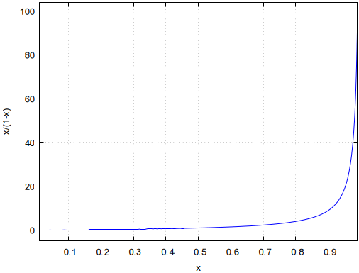
output vs duty cycle

But that's not all: because of the way the flyback works, there is a Volt*sec balance that needs to be considered, and the reflected voltage has a dependency on α exactly like the graph above; it also depends on the value of the primary inductance and the load current. The reflected voltage is the same as the output voltage at the boundary mode. Above it, it will increase, stressing the power switch. The current will also rise, causing extra losses. So it's not a practical aspect to consider.

\$\endgroup\$
2
  • 1
    \$\begingroup\$ DCM duty cycles can be more than 50% and CCM duty cycles can be less than 50%. The boundary condition isn't fixed at 50%. \$\endgroup\$
    – Andy aka
    Commented Mar 9, 2022 at 8:33
  • \$\begingroup\$ @Andyaka You're right, corrected. \$\endgroup\$ Commented Mar 9, 2022 at 9:15

Your Answer

By clicking “Post Your Answer”, you agree to our terms of service and acknowledge you have read our privacy policy.

Not the answer you're looking for? Browse other questions tagged or ask your own question.