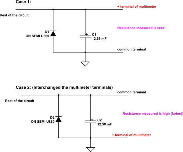
I was trying to understand the connections in a power supply board.
It was found that anode of below diode is connected to GND and -ve terminal of bulk capacitor. Cathode of diode is connected to +ve terminal of bulk capacitor.

simulate this circuit – Schematic created using CircuitLab
One strange measurement result was found when I measured the resistance wrt GND for the 2 cases shown above. The diode orientation is not reflecting correctly while measuring the resistance wrt GND.
Has it got anything with the way the multimeter measures resistance ( by injecting a voltage thereby charging the bulk caps?)
I could find some voltage of 0.2V across diode after the above resistance measurement.
