0
\$\begingroup\$

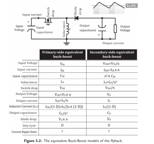
Here is the equivalent buck-boost of flyback converter:

enter image description here

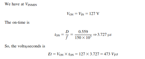
I proved the Volt-Second in a switch-on mode that agrees with the book result (n=22.86.)

enter image description here

In switch-off mode (regarding the above table):

$$t_{off}=(1-D)/f=2.94us$$ $$V_{off}=V_{diode}+V_{OR}=n*V_{D}+n*V_{o}$$

Where \$V_{o}=5V\$

Thus:

  1. If I assume (as we assumed the switch has no drop voltage) \$V_{D}=0V)=>Voff=n*V_{o}=114.3\$ and \$Et=Voff*t_{off}=114.3*2.94us=336us\$ which is not equal to 473us.
  2. If I assume \$V_{D}=1V=>Voff=n*V_{D}+n*V_{o}=22.86+114.3=137.16\$ and \$Et=Voff*t_{off}=137.16*2.94us=403us\$ which is not equal to 473us.

Where is my mistake?

\$\endgroup\$
4
  • \$\begingroup\$ What makes this equivalent to a flyback? This looks like a perfectly ordinary inverting buck-boost converter to me. \$\endgroup\$
    – Hearth
    Commented Apr 30, 2022 at 17:29
  • \$\begingroup\$ Thank you for your comment. regarding the "switching power supplies a to z" book, we can substitute new voltage, current, and components values by reflecting the secondary circuit to the primary circuit by removing the storage transformer. \$\endgroup\$
    – John Jin
    Commented May 1, 2022 at 0:28
  • \$\begingroup\$ @JohnJin can you provide a reference for the images in the post? \$\endgroup\$
    – Voltage Spike
    Commented May 5, 2022 at 4:01
  • \$\begingroup\$ Thank you, I found my problem is that the writer includes Vd in calculating the turn ratios and after that it ignores it. Here is the book: books.google.com/… \$\endgroup\$
    – John Jin
    Commented May 5, 2022 at 9:34

1 Answer 1

2
\$\begingroup\$

At equilibrium or steady-state and in CCM operation, the dc transfer characteristic of the isolated buck-boost converter is \$V_{out}=V_{in}\frac{ND}{1-D}\$. From there, you can extract the operating duty ratio and determine the volt-seconds linked to the on- and off-time duration. At steady-state, they should be equal:

enter image description here

In the equation, \$N\$ characterizes the transformer turns ratio \$1:N\$ and, if made 1, you can determine the values for buck-boost converter since the flyback derives from this structure.

\$\endgroup\$
2
  • \$\begingroup\$ Thank you very much for your explanation. As I checked my equations with yours I see they are the same. In my example \$E_{toff}=V_{off}*t_{on}= n*V_{out}*\frac{1-D}{F_{sw}}\$ where \$n=\frac{1}{n1}\$. But my answer is different ( As you can see my first "If" assumption) \$\endgroup\$
    – John Jin
    Commented May 2, 2022 at 10:04
  • \$\begingroup\$ These equations characterize the inductor volts-seconds balance and are actually used to determine the dc transfer characteristic of any converter: the average voltage across an inductor in steady-state is always 0 V. \$\endgroup\$ Commented May 2, 2022 at 11:56

Your Answer

By clicking “Post Your Answer”, you agree to our terms of service and acknowledge you have read our privacy policy.

Not the answer you're looking for? Browse other questions tagged or ask your own question.