1
\$\begingroup\$

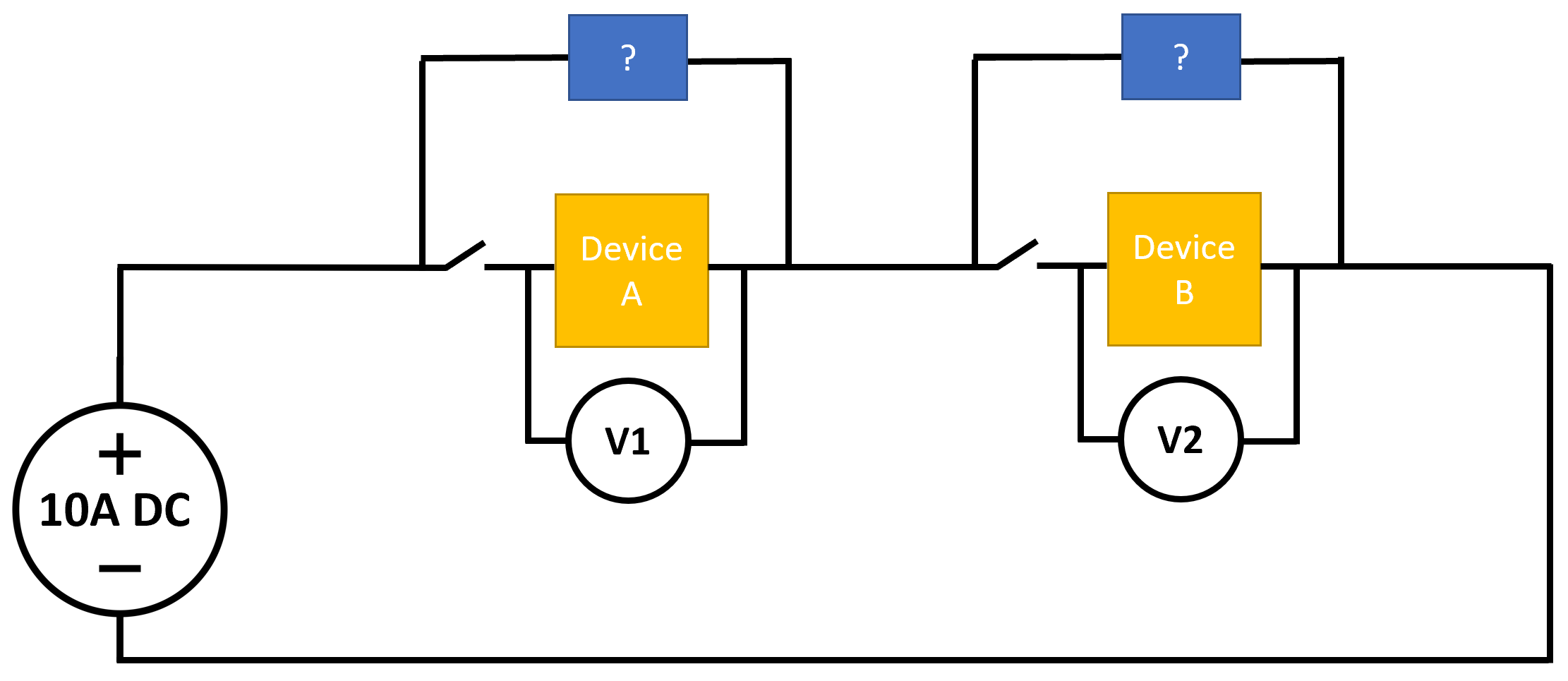
I have high-current devices (10 A) of variable resistance and I am researching their current-voltage behavior over time. I want to operate several devices in series using only a single power supply which delivers a constant DC current of 10 A. However, the voltage drop across each device may never exceed 2.5V as this would cause overheating.

So, here are the requirements for my circuit:

  1. Ideally, 10 A runs through each device (whatever the voltage drop).
  2. If the resistance of a device increases such that the voltage drop would exceed 2.5 V, it should be held at 2.5 V instead (still drawing current - but now less than 10 A).
  3. I should be able to disconnect each device from the series circuit without affecting the others.

Below is a simple depiction of the desired circuit which I hope is helpful. I'm looking for circuit elements that are maybe something like a very-high-power Zener diode. Thank you!

enter image description here

\$\endgroup\$
14
  • \$\begingroup\$ Your Zener diodes are drawn backwards for the effect you are trying to achieve. \$\endgroup\$
    – Transistor
    Commented Jul 10, 2022 at 21:04
  • 1
    \$\begingroup\$ Sounds XY problem. Is your CC/CV power supply not stable for very low voltages? What’s your end goal? \$\endgroup\$
    – winny
    Commented Jul 10, 2022 at 21:05
  • \$\begingroup\$ "The power supply is set to a 10A current limit and a 2.5V voltage limit. So, if the voltage drop across my device at 10A exceeds 2.5V, the device will be held at 2.5V instead and the current is reduced accordingly." 99.99% chance that this sentence is not correct. What you describe is how a voltage-limiting current source works, but there is a 99.99% chance what you have is a current-limiting voltage source. What happens there is the voltage is held at 2.5V as long as the current is below 10A. if the current exceeds 10A then the voltage is reduced to keep the current at 10A. \$\endgroup\$
    – DKNguyen
    Commented Jul 10, 2022 at 21:07
  • 1
    \$\begingroup\$ Your edit still doesn't explain what the problem is that you're trying to solve. What are devices A and B? \$\endgroup\$
    – Transistor
    Commented Jul 10, 2022 at 21:43
  • 1
    \$\begingroup\$ I was hoping not to complicate the problem with too many details. These are electrochemical cells in which water gets split to oxygen and hydrogen. These cells die over time, so I try different chemistries to see which one is most efficient or degrades the least. A good cell generates lots of gas (proportional to the current) at a small voltage drop. The circuit supports this electrochemistry research. \$\endgroup\$
    – Wilhelm
    Commented Jul 10, 2022 at 21:48

2 Answers 2

0
\$\begingroup\$

I have a device that's directly connected to a power supply. The power supply is set to a 10A current limit and a 2.5V voltage limit. So, if the voltage drop across my device at 10A exceeds 2.5V, the device will be held at 2.5V instead and the current is reduced accordingly.

No. If the effective resistance is lower than V/I = 2.5 / 10 = 0.25 Ω then the PSU will limit the current to 10 A and the voltage will fall below 2.5 V.

Can I put my devices in series and replicate similar voltage controls for each device by using circuit elements?

This would generally be a bad idea as series-connected circuits would normally share the same current. You could do it using a "shunt regulator" around each of your loads but that would be difficult with only 2.5 V for the regulator circuit to go on.

Note that your Zener diodes are drawn backwards.

Let all current flow go through Device A if V1 < 2.5V If V1 would exceed 2.5V at 10A, hold it constant at 2.5V instead (whatever the current that flows through) Be able to disconnect Device A from the circuit without affecting Device B.

To power both devices you would need at least 5 V.

This sounds as though you are trying to run two different model LEDs in series. You'd get much better answers if you edit your question to explain the real problem you're trying to solve.

\$\endgroup\$
0
\$\begingroup\$

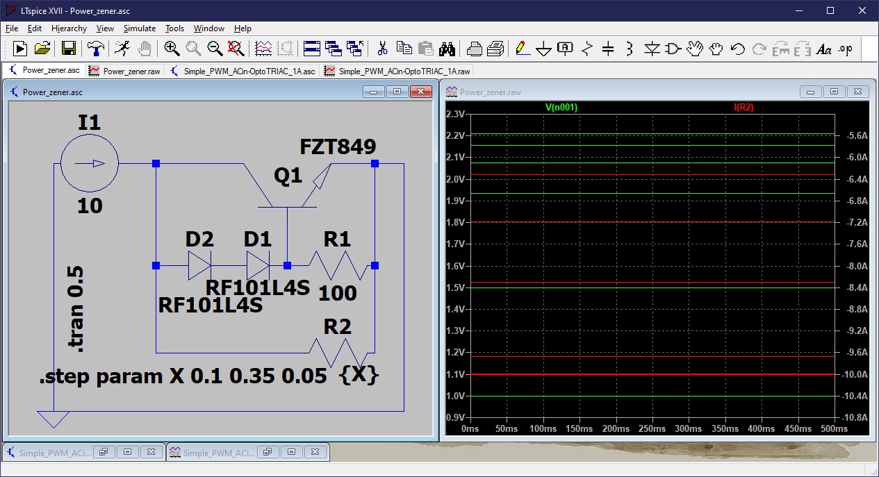
Here is something that seems to work as you require. The voltage across the variable load R2 (which tries to simulate your loads), is limited to 2.2 volts, which is the combined forward voltage of the two diodes D1 and D2, and the base-emitter junction of power transistor Q1. R1 limits current in the diodes to about 267 uA. Changing it to 10 ohms raises the maximum voltage to about 2.35 volts.

Power zener simulation

\$\endgroup\$
2
  • \$\begingroup\$ Thank you very much, this is great. It looks like I'd need a bigger transistor as I believe FZT849 can only dissipate 3W. I am sure I can find suitable ones. If I ever needed to change I1 (say, 5A or 20A), I guess I would only need to change R1? As long as power/current ratings of the diodes and transistor don't get exceeded of course. \$\endgroup\$
    – Wilhelm
    Commented Jul 11, 2022 at 6:06
  • \$\begingroup\$ This same circuit should work just as well for 5 amps and 20 amps. It's basically a shunt regulator like a power zener. You would add another diode to limit voltage to about 2.9 volts. Diodes (and the Vbe of Q1) have a significant negative tempco, so you will need to take that into account. You could actually just use three 10 amp silicon diodes for a 2.1 volt nominal limit, but they will get hot and forward voltage will drop a lot. \$\endgroup\$
    – PStechPaul
    Commented Jul 11, 2022 at 7:24

Your Answer

By clicking “Post Your Answer”, you agree to our terms of service and acknowledge you have read our privacy policy.

Not the answer you're looking for? Browse other questions tagged or ask your own question.