0
\$\begingroup\$

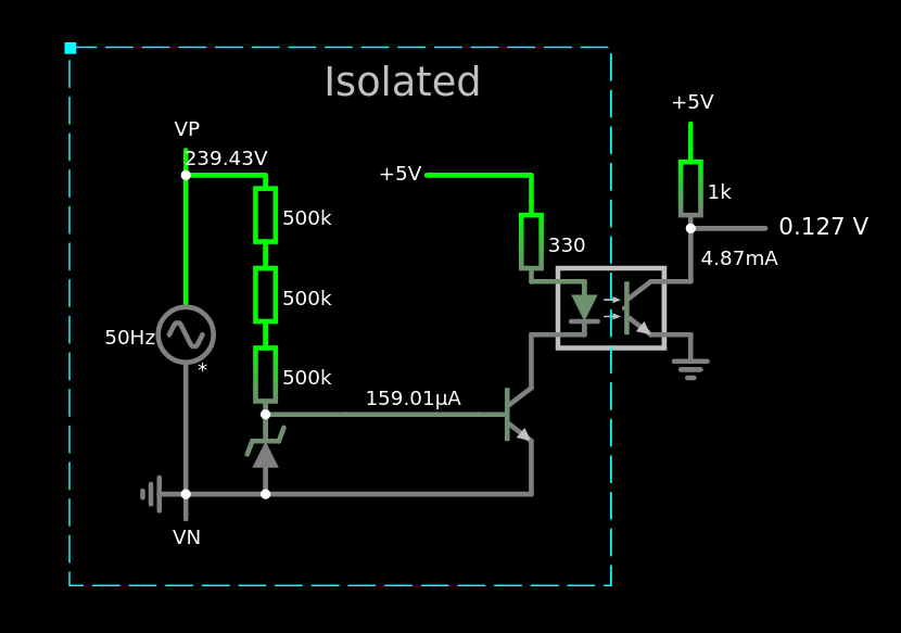
I am trying to work out how to produce an isolated 5 V digital HIGH/LOW of the polarity of a 230 V mains supply.

Basically the aim is to be able to read an amp clamp at a set time interval in order to determine the direction of current flow.

Where I am currently struggling is how to produce the 5 V supply to power the LED of the optocoupler, or maybe the question is how do I power the LED without damaging it or the transistor?

I don't suppose the latency of the changeover detection would need to be particularly accurate as long as it is consistent each cycle.

Would this circuit be safely isolated?

Is there an easier way a 5vm V microcontroller can detect a 230 V polarity change?

enter image description here

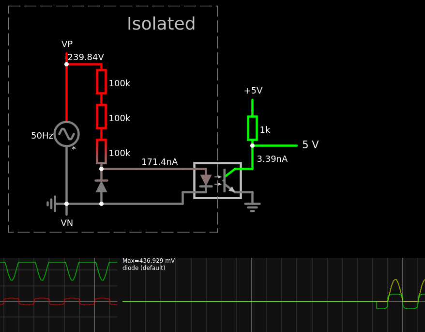
Edit:

enter image description here

\$\endgroup\$
1
  • \$\begingroup\$ why do people that edit my questions add a space between a voltage and the V as in change 230V to 230 V i do not understand why and it bugs me, they don't seem to do it with A for amps and it makes no sense to me and i always feel like changing it back so i can clearly see the V is actually a part of the number like it should be (or at least in my head it should) \$\endgroup\$
    – Jay Dee
    Commented Sep 2, 2022 at 2:36

1 Answer 1

3
\$\begingroup\$

Is there an easier way a 5v microcontroller can detect a 230v polarity change?

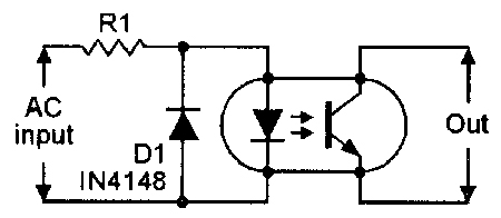
This is a pretty normal way to detect the polarity of the AC mains supply: -

enter image description here

You don't need a transistor or isolated 5 volt supply on the "live" side. You just need a dropper resistor (or capacitor and resistor) plus an LED reverse protection diode (so that the LED inside the opto-coupler doesn't see the full reverse voltage of the mains.

Image from Nut's and volts - OPTOCOUPLER CIRCUITS. The dropper resistor is used to limit the peak current into the opto's LED when the AC voltage is at its peak.

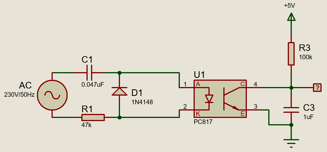
Then there is the capacitor/resistor dropper circuit feeding the opto's LED: -

enter image description here

Image from this question and please note that this circuit was tested by the op and proven to work (read one of the answers). Using a capacitor dropper ensures a higher delivery of current to the opto's LED without dissipating watts of power.

Of course the opto-output circuit needs to be revamped so that you can detect polarity changes on a cycle-by-cycle basis. The important thing here is the 47 nF input capacitor does the main current limiting for the opto's LED without dissipating excessive power.

\$\endgroup\$
4
  • \$\begingroup\$ many thanks. maby i am not grasping something but looking at the output scope in the simulator shot i just added, the output is not digital HIGH LOW it is analog. i tried to incorporate a transistor to sharpen the changeover state hoping for the state to change somewhere near the crossover point. are you saying this is unimportant \$\endgroup\$
    – Jay Dee
    Commented Aug 29, 2022 at 12:18
  • \$\begingroup\$ You might need to amplify the output (or use a comparator) to get a full logic swing. After all, you are only driving the LED with 1.1 mA at the peak of the AC sinewave and, if the CTR of the opto is (say) 70%, the collector current peak will be 0.7 mA and cause only a swing of 0.7 volts p-p at the output @JayDee Opto-couplers like this ARE analogue components; you need a comparator or main gain (clipping) at the output to get digital signals. \$\endgroup\$
    – Andy aka
    Commented Aug 29, 2022 at 13:04
  • \$\begingroup\$ Precisely because the 47 nF drops most of the voltage, it causes a 90 deg phase shift and the output signal will lag the input sinusoid by 90 deg. Be careful how you interpret that signal then. With 100 k load (and change C3 1 uF to 10 nF) you should get 5 Vpp signals, but the rise time will be slow and will need a Schmitt trigger input. \$\endgroup\$
    – jp314
    Commented Aug 29, 2022 at 14:36
  • \$\begingroup\$ "I don't suppose the latency of the changeover detection would need to be particularly accurate as long as it is consistent each cycle" <-- quote from the question. \$\endgroup\$
    – Andy aka
    Commented Aug 29, 2022 at 16:14

Your Answer

By clicking “Post Your Answer”, you agree to our terms of service and acknowledge you have read our privacy policy.

Not the answer you're looking for? Browse other questions tagged or ask your own question.