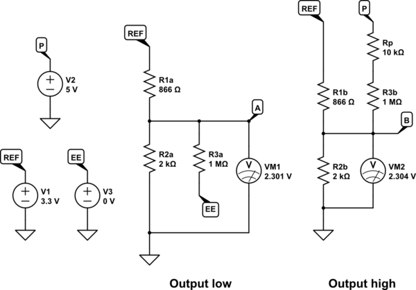
I can't recommend simulation strongly enough. All questions answered with a couple of quick models, one for when the comparator output is low, one for when it's high:

simulate this circuit – Schematic created using CircuitLab
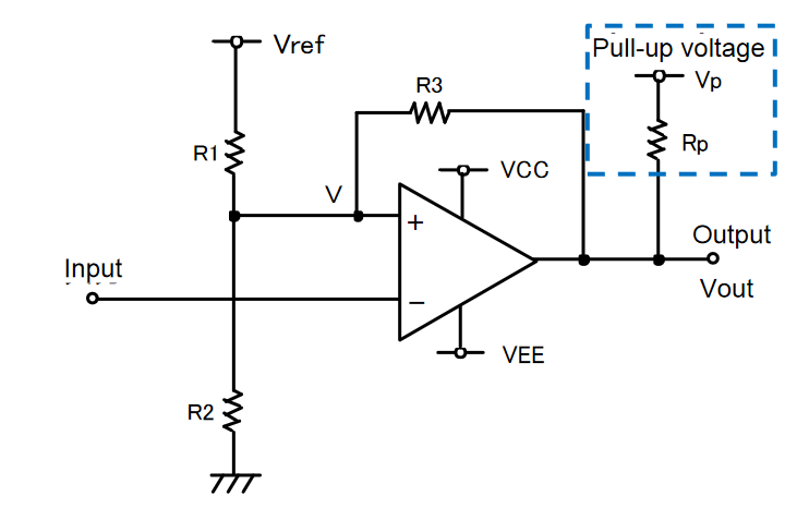
In the "Output low" model Rp is ignored, because the comparator's output is connected (almost) directly to \$V_{EE}\$, and feedback is via R3 alone.
In the "Output high" model, the comparator's output is effectively disconnected from everything (due to its open collector), and the high output is provided by the combined efforts of Rp and R3, pulling up to \$V_P\$
The reason it is recommended that \$R_3 >> R_P\$ (by a factor of 100, at least) is to ensure that feedback path impedance doesn't change much between the two output states. With these models it becomes clear that effective feedback impedance changes between 1.00MΩ and 1.01MΩ. The effect of the absence or presence of \$R_P\$ in the calculations is very small, only 1%, and can be neglected.
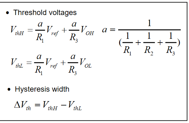
From the voltmeters it's also clear that your calculations are correct; there's a difference of only 3mV between thresholds.
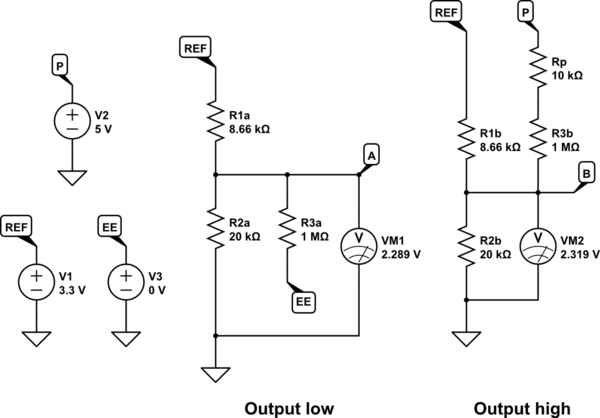
To increase hysteresis (the difference between the two threshold potentials), all you need to do is allow feedback to have a bigger influence on the potential at the junction of R1 and R2, either by increasing R1 and R2, or decreasing R3.
With an understanding of the principle of superposition, you could guess that increasing R1 and R2 by a factor of 10 will make it ten times "easier" for R3 to modulate the potential at their junction, increasing hysteresis by the same factor. And your guess would be right. So by setting R1 = 8660Ω, and R2 = 20kΩ, you can expect hysteresis to become about 30mV:

simulate this circuit


