3
\$\begingroup\$

I have designed a window comparator and am finding it seemingly impossible to add hysteresis. Below is the basic circuit before attempting to add hysteresis. enter image description here
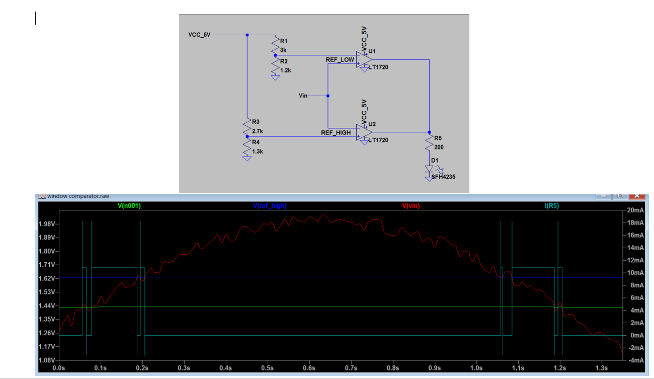
Now I add a feedback resistor to the positive input of both op amps in an attempt to add hysteresis and this is the result: enter image description here
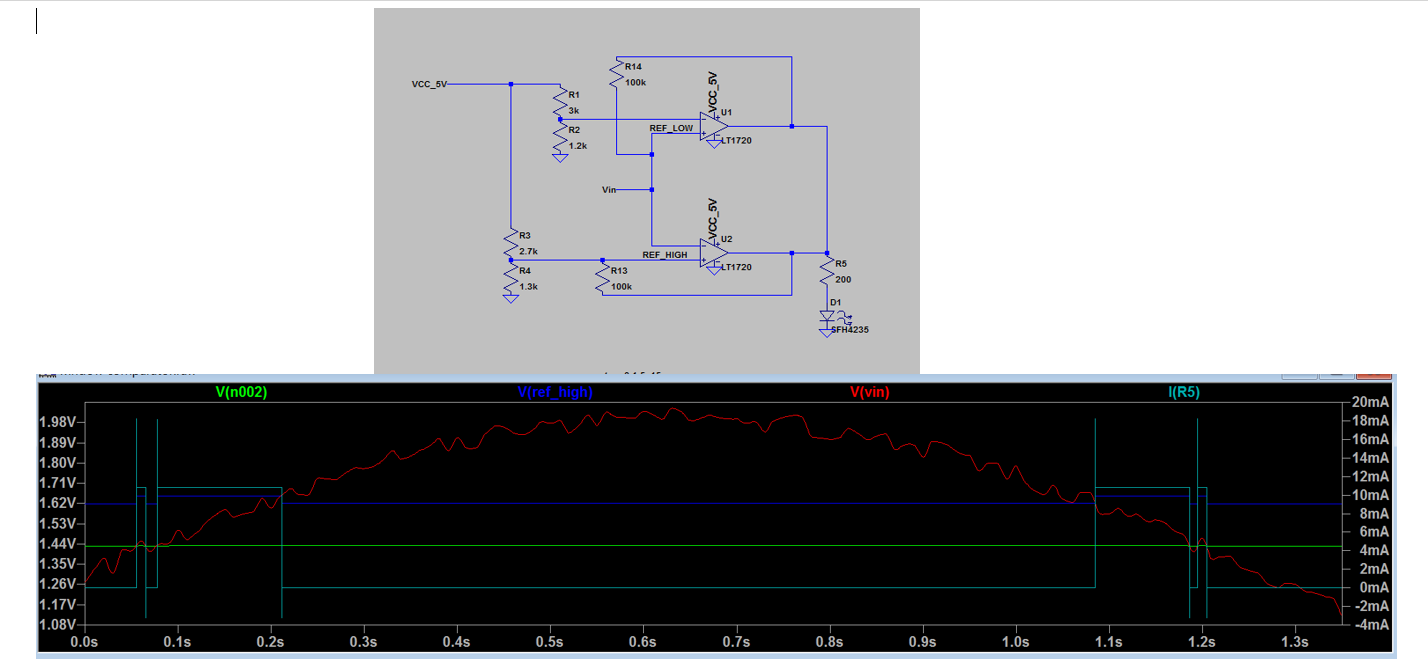
The hysteresis seems to only be applied to U2, where the reference voltage is on the positive input. When the reference voltage is on the negative input, as it is for U1, it doesn't do anything. Putting the feedback resistor for U1 on the negative input screws up the whole thing too. This is what is confusing me. Is there a way to do this? The reason I want to add hysteresis is because the LED flickers when you are near the reference voltages, since the input voltage is from an accelerometer and is very sensitive to change.

\$\endgroup\$

3 Answers 3

2
\$\begingroup\$

The reason is probably because Vin is driven with relatively low resistance.

If you want approximately the same amount of hysterisis on U1 comparing to U2, a simple way would be to put the equivalent of R3||R4, around 1.1K 878\$\Omega\$, in series of Vin coming in.

There is a small side effect of doing that -- it does shift the high ref level a little, which you can compensate if you want.


In my original answer above, I didn't see the easy connections to not have the positive feedback from U1 affecting U2. The connections should be Vin through a resistor to + pin of U1 and Vin directly (not through the resistor) to the - pin of U2.

\$\endgroup\$
4
  • \$\begingroup\$ Of course Rsource=~0, then Rs/(Rs+Rf) = 0% of output= Hysteresis \$\endgroup\$
    – D.A.S.
    Commented Oct 28, 2016 at 12:50
  • \$\begingroup\$ How do you compensate for the fact that U2 is essentially receiving both positive (R13) and negative (R14) feedback at the same time? \$\endgroup\$
    – Brad Thiel
    Commented Oct 28, 2016 at 22:58
  • \$\begingroup\$ rioraxe, when you connect Vin directly to - pin of U2, and Vin through a resistor to + pin of U1....does the value of the Vin resistor stay the same as in your original response (R3||R4). Could you also share the equations used to find that Vin resistor value? \$\endgroup\$
    – Brad Thiel
    Commented Jan 11, 2017 at 4:56
  • \$\begingroup\$ The thevenin equivalent for (R3 and R4) is R3||R4 = 1/(1/R3+1/R4) = 878. When combined with the 100K fb resistor gives a hyteresis ratio of around 0.0087 or 43mV when multiplied by 5V swing for U2. So if you want the same hysteresis ratio for U1, use a 878 resistor between Vin and U1 + pin. \$\endgroup\$
    – rioraxe
    Commented Jan 11, 2017 at 9:11
1
\$\begingroup\$

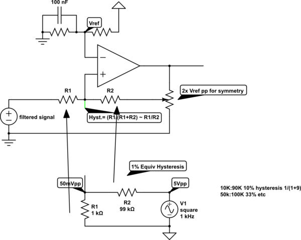
The solution for hysteresis uses the same "design logic" with R ratios as you would for gain with negative feedback except using positive feedback.

  • The key here is to introduce a controlled source impedance and feedback R to give the desired ratio , e.g. 1% 1K source 100k feedback
  • The other key is you need to modify the full scale deflection of the output so that your input signal must be always mid-scale to the full scale output ( attenuated by R ratios if necessary)

schematic

simulate this circuit – Schematic created using CircuitLab

  • if the input signal has a poor SNR then it is wise to analyze the "useful" bandwidth of the signal and design a filter to match that spectrum, and notch the noise if possible.
    • e.g. 4th order 5Hz LPF using dual OP Amp and 4 RC values
  • If the noise is "mechanical" then add stiffeners.

Note the LT1720 has 2~7mV hysteresis and your signal has 100 mVpp noise while your thresholds are only 200mVpp apart. So although possible to make a clean toggle, I would reduce the noise 5:1 and increase hysteresis to 20mV

\$\endgroup\$
0
\$\begingroup\$

Very late to the party here, but I agree with the other answers. The Vin fed to the non-inverting input must have some resistance in series with it in order for the positive feedback resistor to be able to effect the voltage on that non-inverting input. One other thing that should be pointed out is that the comparator being used (LT1720) has active drive high as well as low (it doesn't need a pullup resistor). This type of comparator should not be connected in a wired-or fashion (both outputs tied directly together) as that will create an output contention situation when one comparator wants to drive high and the other one wants to drive low. For this type of application, open-collector/drain output comparators should be used instead.

\$\endgroup\$

Your Answer

By clicking “Post Your Answer”, you agree to our terms of service and acknowledge you have read our privacy policy.

Not the answer you're looking for? Browse other questions tagged or ask your own question.