1
\$\begingroup\$

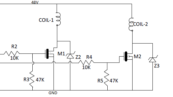
I am working on the following circuit. This circuit is the driver of a two-pole DC motor using a MOSFET as a switch. The coil voltage is 48 V.

  1. MOSFET M1,M2 = STB4NK602T4
  2. Coil1 & coil2 (two-pole motor) = 23 Ω (load curreng = 2.1A @ 48V)
  3. TVS Z2,Z3 = 3.0SMCJ170A

enter image description here

My questions are:

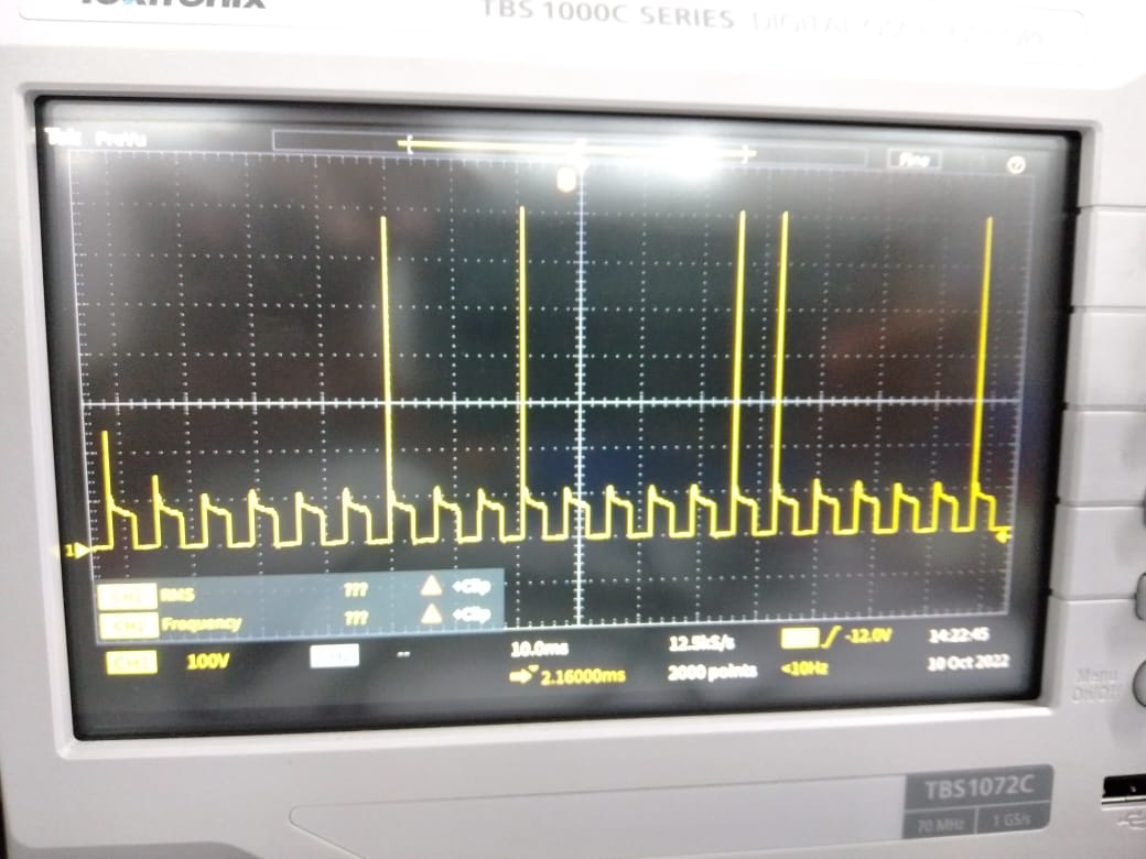
  1. Without using TVS diodes Z2 & Z3, why are the MOSFETs getting too hot at 150 Hz switching frequency with VGS = 10 V? Im measuring at the drains (load) of the MOSFETs.

enter image description here

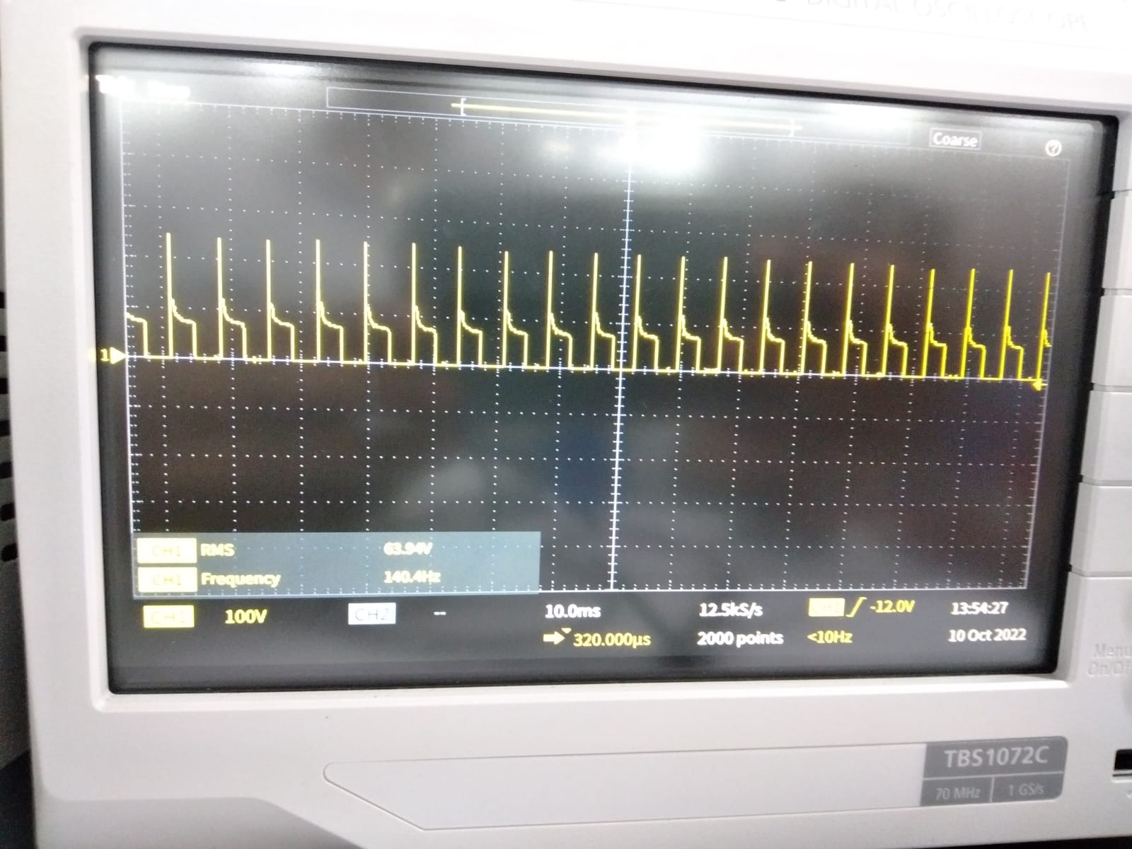
I think that the heat is because of this kind of irregular spikes; those spikes are higher than 600 V. How can I remedy this? What is the source of these spikes? Is this due to the inductive nature of load? 2. When I make thr switching frequency 90 Hz, then there is no MOSFET heating. 3. When I use the following TVS diode then we got this waveform, but in this case the TVS is getting very hot. Also, the spike voltage is reduced, but my output RPM also gets reduced.

enter image description here

\$\endgroup\$
1
  • 1
    \$\begingroup\$ R2 & 4 being 10k is too high in value causing the mosfets to switch slowly and getting hot. \$\endgroup\$
    – Kartman
    Commented Nov 7, 2022 at 12:33

2 Answers 2

2
\$\begingroup\$

Is this due to the inductive nature of load?

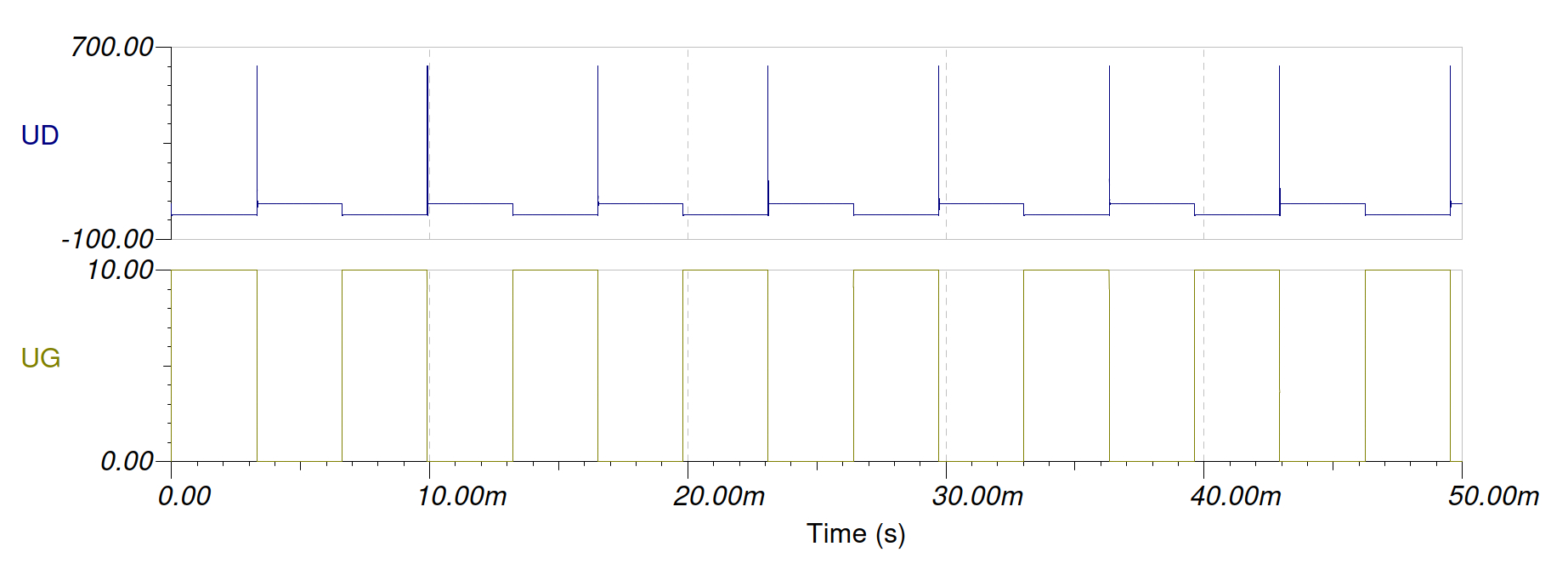
Yes, that's exactly what we see. A common characteristic of inductive loads is that when current flows through them and the circuit is turned off, the inductor produces a high voltage peak. The voltage is determined by the drain-source breakdown voltage (600 V) of the FET. The current decreases exponentially from the interrupted current value. The power will heat the FET. If we put a TVS diode here, we only achieve that the TVS with a lower voltage than the FET heats up instead of the FET. It will be a significantly better solution if this current is fed back into the coil with a (fast) diode. This will make the voltage peaks disappear.

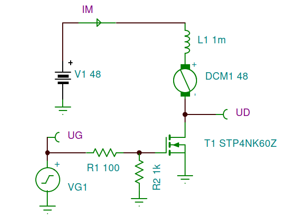
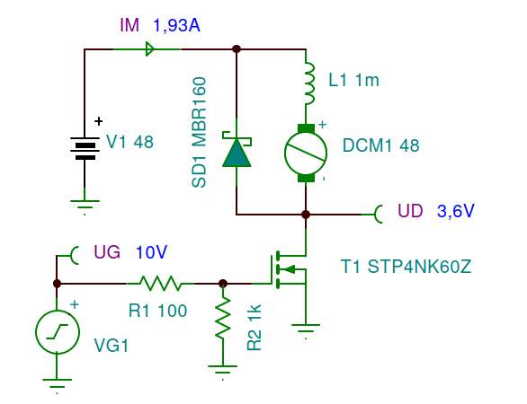
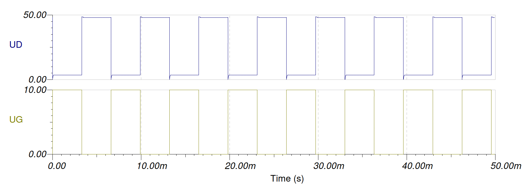
This is what the simulation looks like without and with a diode: (The resistor values were too large to charge and discharge the input capacitance of the FET, so I reduce them.) enter image description here enter image description here enter image description here enter image description here One problem persists. The drain source resistance of the FET is too high for such a current. Dissipation on the continuously on FET is 6.9 W. It needs a serious heatsink.

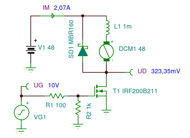
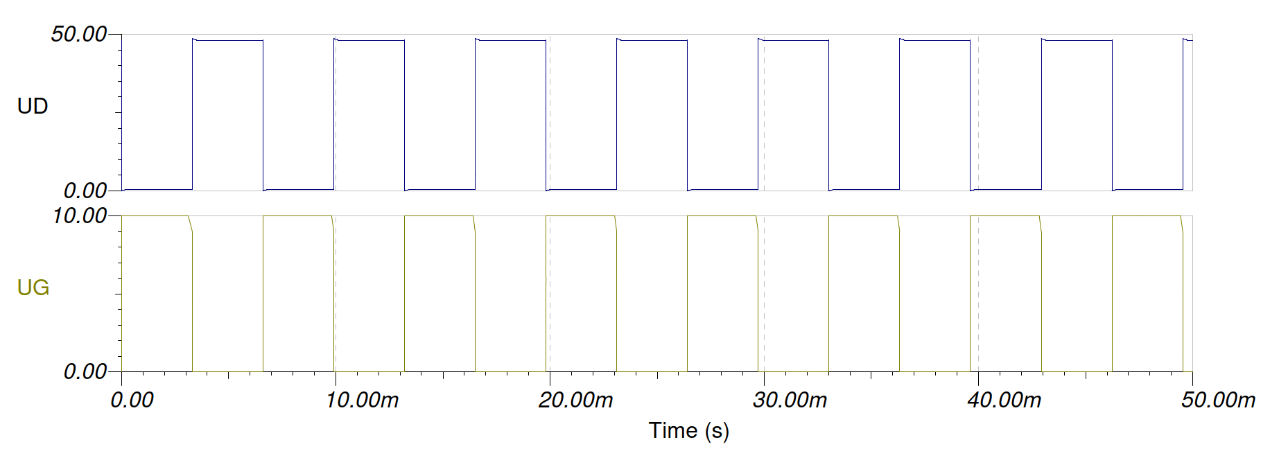
By choosing a more practical FET, it can work continuously even without a heatsink (670 mW). enter image description here enter image description here If possible, choose a FET with a small input capacitance. Very low resistance FETs have an input capacitance of around 5 nF, which is too high for such gate control.

\$\endgroup\$
2
  • \$\begingroup\$ thanks sir, it is so much helpful. Which tool you used for a simulation \$\endgroup\$ Commented Nov 8, 2022 at 15:34
  • \$\begingroup\$ Here I used the TINA (TINA-TI) simulation program. \$\endgroup\$
    – csabahu
    Commented Nov 8, 2022 at 16:39
2
\$\begingroup\$

The spikes occur every time the FET turns off. They are short enough that the scope resolution will not display in them all.

When the FET turns off, the coil current must continue. The voltage increases until the TVS breaks over. If the TVS is removed, the FET will break over at something that greater than 600V according to the data sheet.

The best solution is to place a Schottky diode across each of the coils. Cathode to supply rail and anode to the drain. This will allow the coil current to be directed back to its other end.

This method will prevent the spikes from occurring. The TVS devices are not necessary here.

\$\endgroup\$

Your Answer

By clicking “Post Your Answer”, you agree to our terms of service and acknowledge you have read our privacy policy.

Not the answer you're looking for? Browse other questions tagged or ask your own question.