0
\$\begingroup\$

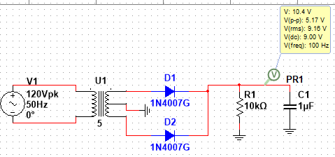
I am given the circuit shown below, a full wave rectifier with a filter.

enter image description here

To find the DC output on a full wave rectifier with a filter, I was given the formula: $$V_{dc}(out) = \frac{V_{M}}{1+\frac{1}{2RCf(out)}}$$ Where Vm is the peak output on the resistor.

However theoretically the Vm across load is 11.3V and my output yields, $$V_{dc}(out) = \frac{11.3}{1+\frac{1}{2*10*10^3*1*10^6*100}}$$ $$V_{dc}(out) = 7.53V$$

Where did I go wrong?

I also have another confusion where I have derived the formula: $$V_{p-p}(ripple)=\frac{V_{DC}(out)}{RfC}$$ Using the DC value from Multisim I wasn't able to get the Vpp as it remained 9V same as the DC.

\$\endgroup\$
5
  • 2
    \$\begingroup\$ electronics.stackexchange.com/questions/636422/… \$\endgroup\$
    – Antonio51
    Commented Nov 12, 2022 at 18:13
  • 1
    \$\begingroup\$ Arcadius, Spehro pretty much gives you the right short-hand answer with the important qualitative points and a quantitative change to the ripple equation you were given (or remembered), which is wrong by a factor of 2. If you want to read how to develop such an equation on your own, you can look here. But keep in mind to get it huge assumptions are made that the capacitor is supplying current throughout the half-cycle once it is charged up at the cycle peak and that discharge is linear throughout. Almost always predicts too large a value. \$\endgroup\$
    – jonk
    Commented Nov 12, 2022 at 21:11
  • \$\begingroup\$ The very first time I used this circuit, I had only "Schade" charts. \$\endgroup\$
    – Antonio51
    Commented Nov 13, 2022 at 8:37
  • \$\begingroup\$ Thank you, @Antonio51 and @jonk! That source was really helpful. I do want to learn to develop my own equation for practice. \$\endgroup\$
    – Arcadius
    Commented Nov 13, 2022 at 16:10
  • \$\begingroup\$ I forgot the link for Schade charts ... hifisystemcomponents.com/downloads/articles/schade.pdf \$\endgroup\$
    – Antonio51
    Commented Nov 13, 2022 at 21:01

2 Answers 2

2
\$\begingroup\$

That formula you were given doesn't make a lot of sense for low RC. Average Vout with no capacitor will be Vm*(2/π) not zero.

Your second equation is wrong. There needs to be a factor of 2 in the denominator for a full-wave rectified circuit. Again, it doesn't make sense for relatively low RC since the output current will be less constant. The result with the factor of 2 inserted is 11Vp-p and reality is almost half of that.

I always derive these from first principles as needed because it avoids such mistakes and reminds of the assumptions behind the formula (modeling the ripple as a triangle at 2f). For reasonable ripple this is easiest and leads to a conservative answer for the ripple (tends to give a higher number than simulation, leading to selection of a larger capacitor).

\$\endgroup\$
2
  • 1
    \$\begingroup\$ Agreed, it should be \$\Delta\,V_\text{C}=\frac{I_\text{LOAD}}{2f\,C}\$. But of course that also isn't right because to get that equation we had to assume that the entire period is spent discharging the capacitor into the load. So just as you say, this means even that equation predicts a higher ripple than would actually be experienced. I also agree with using the equation to bound the problem. You know that it must be better than that. Engineers generally do not need or require a more sophisticated equation to make more accurate prediction from theory. (A physicist or mathematician may.) +1 \$\endgroup\$
    – jonk
    Commented Nov 12, 2022 at 21:06
  • \$\begingroup\$ @Spehro Pefhany that's right I haven't realized that the low capacitance had a faster discharge before the rectified sine wave picked up again, hence the assumption that its DC output is basically a rectified full wave without a filter. I have tried simulating the circuit again using varying resistances and capacitances and it really did show accuracy in a specific range and only in ideal conditions. \$\endgroup\$
    – Arcadius
    Commented Nov 13, 2022 at 16:17
0
\$\begingroup\$

One problem is, there is no "DC output" there is ripple and so it's likely that there are differences in calculating exactly what the average is. Another difference is multi sim is using an actual model, it appears that the Vdc_out calc of 7.35V uses a diode drop of 0.7V, whereas the multisim model will have a better diode model that could account for some of the differences.

\$\endgroup\$
2
  • \$\begingroup\$ is there an ideal diode model with specified voltage drop in Multisim? I have looked into it to no avail. The only clue I got was to reduce the Emission Coefficient which makes it ideal with no voltage drop. \$\endgroup\$
    – Arcadius
    Commented Nov 13, 2022 at 16:25
  • \$\begingroup\$ Probably, most simulators do I've never used their ideal diode model. I have used the ideal diode in LT spice \$\endgroup\$
    – Voltage Spike
    Commented Nov 13, 2022 at 18:04

Your Answer

By clicking “Post Your Answer”, you agree to our terms of service and acknowledge you have read our privacy policy.

Not the answer you're looking for? Browse other questions tagged or ask your own question.