0
\$\begingroup\$

I have been trying to make some sense of a parallel AC RL-C circuit for over a week now.

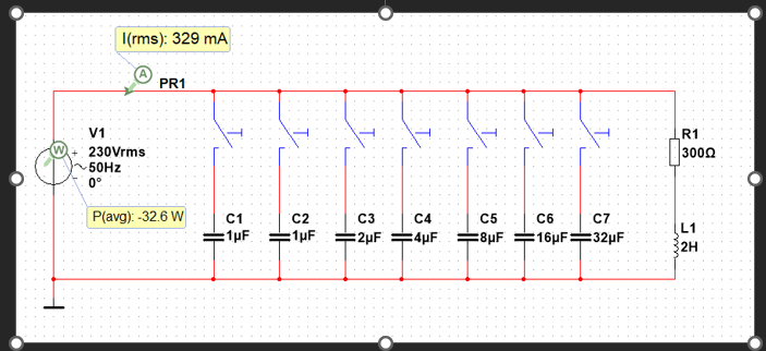
Image of the circuit

The question asks "Measure the current and active power absorbed by a lamp (simulation circuit below and practical setup in the lab) without such a capacitor, and calculate the PFC required."

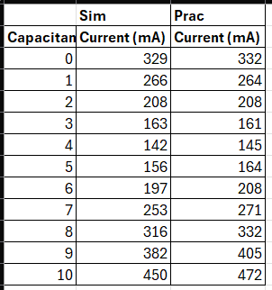
I have simulated it in Multisim and also done a practical for this in college classes. From both of these the results are as follows:

enter image description here

If I simulate the capacitor value to be at 4 μF then the circuit is very close to being in phase, but when I calculate the capacitor value, I get a different value.

XL=2πfL

XL=2π(50)(2)=628.319 Ω

C=1/(2πfXC)

C=1/(2π(50)(628.319)) = 5.066 μF

If I then simulate with this value the phase and power factor of the circuit are less than when using just a 4 μF capacitor.

fr = 1/2π√LC

fr = 1/2π√(2)(5.066 μF) = 50.0003 Hz.

Can someone check my math or simulation and confirm if these are correct or if I am missing something or using the wrong equation somewhere?

I have also checked this simulation in MATLAB and get the same values as in Multisim.

\$\endgroup\$
3
  • \$\begingroup\$ Minimum current won't correspond to unity power factor in your circuit. \$\endgroup\$
    – Andy aka
    Commented Feb 22 at 23:24
  • \$\begingroup\$ @Andyaka Why wouldn't it? \$\endgroup\$
    – Puk
    Commented Feb 23 at 0:11
  • \$\begingroup\$ @Puk see my answer for why. \$\endgroup\$
    – Andy aka
    Commented Feb 23 at 9:25

2 Answers 2

1
\$\begingroup\$

You are adding the capacitor in parallel with your load impedance, not in series. As such, the load and capacitor reactances don't add to yield the equivalent reactance, so you can't set \$|X_L| = |X_C|\$ to find the capacitance that makes the equivalent reactance zero. It is the susceptances (the imaginary parts of the admittances) that add.

The load impedance is \$Z_L = R + jX_L\$, so the load admittance is $$Y_L = Z_L^{-1}=\frac{1}{R+jX_L}=\frac{R-jX_L}{R^2+X_L^2},$$ and the load susceptance is $$B_L=\text{Im}\{Y_L\}=-\frac{X_L}{R^2+X_L^2}.$$ The capacitor susceptance \$-1/X_C=2\pi fC\$ must be equal to negative \$B_L\$ to cancel it out, so $$ C = \frac{X_L}{2\pi f(R^2+X_L^2)}=\frac{L}{R^2+(2\pi fL)^2}=4.13\ \mu\text{F}.$$

\$\endgroup\$
0
\$\begingroup\$

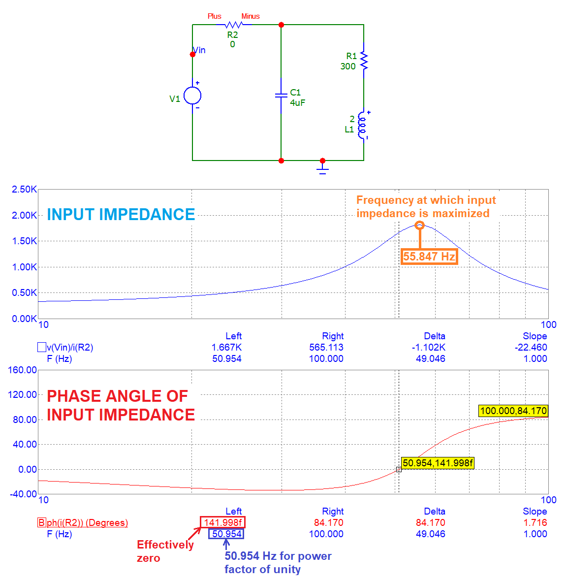
A simulation sure would help to explain why the frequency at which unity power factor exists is different to the frequency at which the net current is minimal: -

enter image description here

I've used 4 μF for the PF correction capacitor and, it's nearly right but not quite but, the whole point of the above is to explain that minimum current won't correspond to unity power factor in your circuit.

This means you can't use the solution of a simple tuned circuit to find the value capacitance because, it gives you an error. The actual value of capacitance that gives you unity power factor at 50 Hz is 4.1256 μF.

You can prove this by developing a formula for the input impedance and then equating the imaginary part to zero. Or, perhaps a simpler approach would be to convert the series R and L to parallel form then solve using the resonant frequency formula for an ideal tuned circuit. There are a few on-line calculators that can help you out here.

I'll leave it for you to solve.

\$\endgroup\$

Your Answer

By clicking “Post Your Answer”, you agree to our terms of service and acknowledge you have read our privacy policy.

Not the answer you're looking for? Browse other questions tagged or ask your own question.