1
\$\begingroup\$

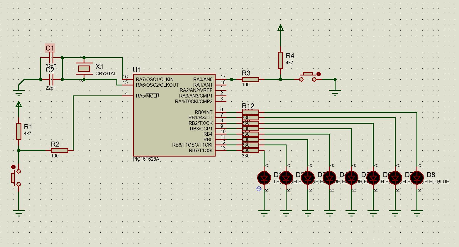
I am using PIC16F628A, MPLAB IDE to coding and Pickit3 to write the code into MCU. The code works on Proteus but does not in real world. I setted A0 pin as input. It should count up normally and count down when button pressed. It count down when button pressed but don't count up. So the pin don't recognize 5 V input or something else.
//CONFIG

#pragma config FOSC = XT        // Oscillator Selection bits (XT oscillator: Crystal/resonator on RA6/OSC2/CLKOUT and RA7/OSC1/CLKIN)

#pragma config WDTE = OFF       // Watchdog Timer Enable bit (WDT disabled)

#pragma config PWRTE = OFF      // Power-up Timer Enable bit (PWRT disabled)

#pragma config MCLRE = ON       // RA5/MCLR/VPP Pin Function Select bit (RA5/MCLR/VPP pin function is MCLR)

#pragma config BOREN = ON       // Brown-out Detect Enable bit (BOD enabled)

#pragma config LVP = OFF        // Low-Voltage Programming Enable bit (RB4/PGM pin has digital I/O function, HV on MCLR must be used for programming)

#pragma config CPD = OFF        // Data EE Memory Code Protection bit (Data memory code protection off)

#pragma config CP = OFF         // Flash Program Memory Code Protection bit (Code protection off)


#include <xc.h>

#define _XTAL_FREQ 4000000

void main(void){
    int count=0;
    
    TRISB = 0x00;
    TRISAbits.TRISA0 = 1;
    
    PORTB = count;
    while(1){
        
        if (RA0==1){
            count = count+1;
            PORTB = count;
            __delay_ms(100);
        }
        
        else {
            count = count-1;
            PORTB = count;
            __delay_ms(100);
        }
    }
}

\$\endgroup\$
2
  • \$\begingroup\$ Anyway it's not really possible to tell what the problem might be. Measure the input with a volt meter, does it say 5V? \$\endgroup\$
    – Lundin
    Commented Dec 12, 2022 at 11:11
  • \$\begingroup\$ Yes voltage is 5v \$\endgroup\$
    – akiftokel
    Commented Dec 12, 2022 at 11:12

1 Answer 1

2
\$\begingroup\$

Not certain on this, because I haven't used the 16F628 before.

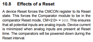
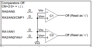
PIC GPIOs usually default to analogue inputs, so you may need to configure the CMCON register to turn off the analogue comparators, so that they become digital I/O pins.

Excerpts from the datasheet - https://ww1.microchip.com/downloads/en/DeviceDoc/40044G.pdf

enter image description here

enter image description here

This note indicates that the GPIO would always read as 0.

enter image description here

\$\endgroup\$
2
  • \$\begingroup\$ I add "CMCON = 111;" it worked. Thank you \$\endgroup\$
    – akiftokel
    Commented Dec 12, 2022 at 14:39
  • \$\begingroup\$ @akiftokel Good news. \$\endgroup\$
    – HandyHowie
    Commented Dec 13, 2022 at 7:50

Your Answer

By clicking “Post Your Answer”, you agree to our terms of service and acknowledge you have read our privacy policy.

Not the answer you're looking for? Browse other questions tagged or ask your own question.