2
\$\begingroup\$

A few years ago someone told me that if you use a cable which has a length of an even half-wavelength multiple for the frequency being tested, then the impedance measured at the end of that cable will be the same as if it were measured at the feedpoint. For example (assuming you account for velocity factor) a 2-meter wavelength antenna should be measured with a cable that is in even 1-meter increments.

...but then I began to question just what it means to calibrate a VNA with respect to cable length from the VNA to the DUT, since I would think that the calibration including the feedline to set the reference plane would take care of that detail. Now I wonder if there is value to a \$\frac{\lambda}{2}\$-multiple cable length.

There are a few possible ways that I can think of to calibrate:

  1. Calibrate at the VNA's SMA port and tie the VNA directly to the DUT. This may be impractical if proximity effects DUT behavior (like an antenna).

  2. Use an arbitrary length of feedline (that is not based on wavelength) and calibrate the VNA with a reference plane at the end of that feedline.

  3. Calibrate the VNA at its SMA port and use an even \$ \frac{\lambda}{2} \$-multiple-length of feedline to connect to the DUT.

  4. (Obviously this 4th item isn't a good idea because it will rotate around the Smith chart by an unknown angle, but I have included for completeness: Calibrate the VNA at its SMA port and use an arbitrary length of feedline.)

Questions:

  • Except for round-trip time delays added by the cable length, are #2 and #3 effectively the same in terms of impedance? Otherwise stated: if you make an "good" impedance match having measured with method #2 will that match be the same as if you had measured with method #3?

  • If they are not the same, then why?

  • Are there any benefits to using a \$ \frac{\lambda}{2} \$-multiple-length of feedline with a VNA?

(In our specific application we are measuring the feedpoint of a huge helical antenna in the 2m and 70cm bands for a student satcom project. Helical antennas are in the usually 140 to 170-ohm range depending on spacing and other details.)

\$\endgroup\$
3
  • \$\begingroup\$ The helix spiral looks good in your video as long as it doesn't vibrate. Tolerance errors must be in the xx PPM for Q> 1000. But that's hard to get more than 26 dB gain. Good question. New idea from me. \$\endgroup\$
    – D.A.S.
    Commented Dec 13, 2022 at 16:15
  • \$\begingroup\$ I worked with a Quebec farmer in Winnipeg who designed all Bell's uwave stuff and his claim to fame for thousands of repeaters was a 3.25 dB splitter vs 3.5 dB or 0.25 dB improved times a thousand repeaters , that's a cost savings of 250 dB of repeater spacing gain. \$\endgroup\$
    – D.A.S.
    Commented Dec 13, 2022 at 16:23
  • \$\begingroup\$ For some reason, I have been told to use approximately lambda/4 line wired between VNA output and DUT ... when the frequency is "fixed". \$\endgroup\$
    – Antonio51
    Commented Dec 14, 2022 at 13:22

1 Answer 1

0
\$\begingroup\$

The helical antenna also has Q's up to the 1000 range or high gain.

Yes, it is true that end impedance is not transformed to a different value using even wavelengths tuned for maximum return loss using a DC-20 or similar and Sch. diode to DVM or NA.

You can improve your overall Return Loss by tuning the length near even half waves. (longer adds more capacitance, shorter more inductive) Using a semi-rigid coax works well for tuning cable extended lengths as it is high quality and easily trimmed with an exact knife and tool then resoldered. Then you might need connector adapters to SMA. Not all RG58 is the same quality and stiffer types tend to be better so Coax used for Sat TV are preferred.

You know that a matched impedance supports maximum power transfer at 50% loss.

So how can I do better?

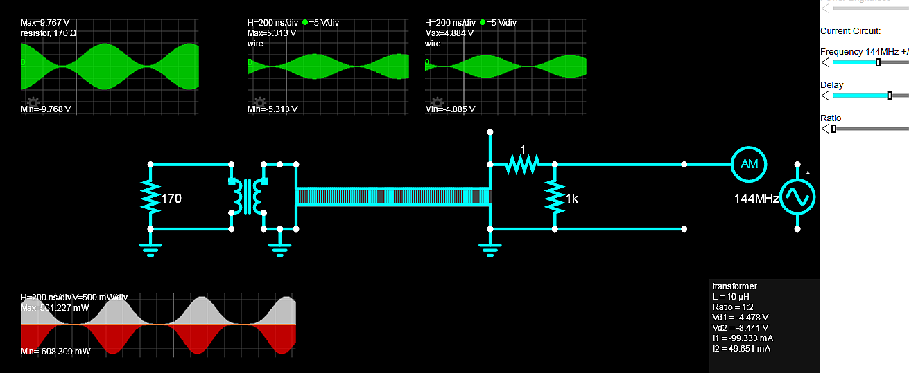
Well if the antenna is 170 Ohms and I reduce the source towards 0 and then use a step-up transformer with an ideal inductance at 10uH and turns ratio = 1:2 with a 75 ohm coax in between tuned for 144 MHz with the cable tuned to 8.04m at 41.26ns one can gain a couple more dB. The coax was chosen at roughly the square route of source * load impedances and Satellite 75 ohm Coax is cheap. But if you afford solid or semi-rigid Cu coax, that's better.

enter image description here

The Red white plot shows power generated as negative at 608 mW pk from 5V thus Zin = V^2/P= 41.1 ohms into a 75 Ohm cable to a 1:2 10 uH transformer to a 170 ohm antenna resistive load (?) The modulation at 1 MHz shows the delay of 4 wavelengths at 144 MHz or 160 ns or 16% of 1 us.

The efficiency with 558 mW out/ 608 mW in = 91.7%

What did I do wrong? Does this violate MPT?

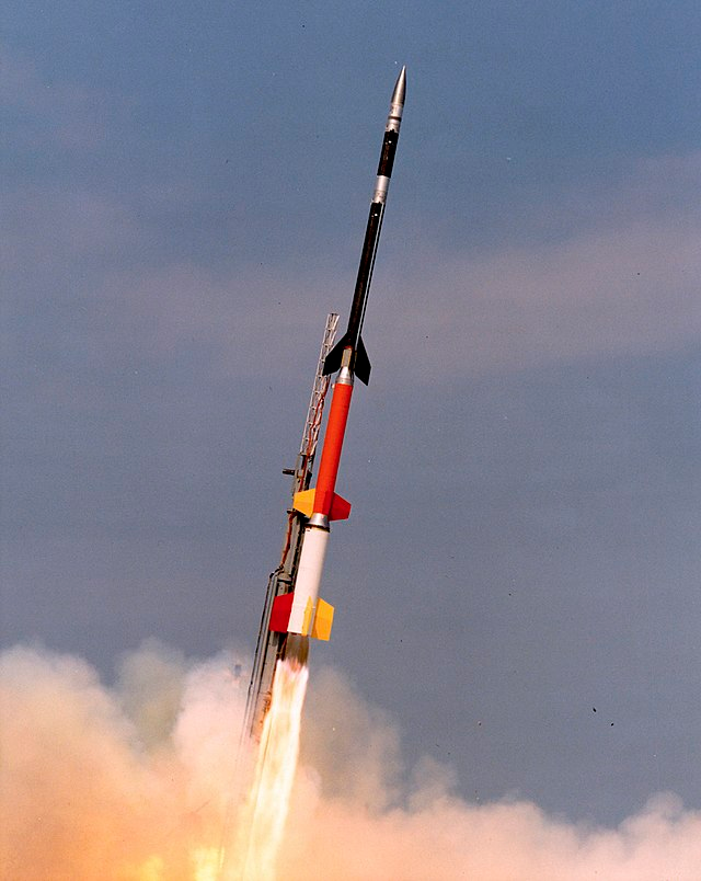
Back in the late '70s when I designed SCADA and Doppler instruments as well as antennae for Nuclear and Aerospace. When we launched rockets in Churchill MB by Hudson's Bay, they had big rooms filled with wall-to-wall racks of telemetry equipment and a huge array of antennae. We chose the massive tracking Quad Helix to get VHF signals from 550 Miles up. Only when the rocket was falling near the horizon on a parachute did we have LOS every half rotation but the plasma experiments of Aurora were over then. My little OXCO was to replace the trailer full of WWII TRACS RADAR equipment with 2 men operating it. The next day we site Polar Bear tracks bigger than my massive size 12 goulashes and spaced apart from running in 1m of snow by about 3m. These bears can run 25 MPH in a short sprint. So I had to man the manual single helix antenna for my Doppler sub-carrier 100kHz FM channel on the UHF telemetry band, ... because my Tech was chicken. Awesome place. We play pool, swam, skated, bowled, played volleyball or drank at the Hotel bar during the day, then worked 4 hrs at night waiting for the right Aurora determined by the Chief Scientist from Plasma Physics NRC. NASA would be in the next bay working on their solid rocket too but ours (Bristol) worked better. A BBIV would leave the launch tower at 200 MPH and reach Mach 7 in a minute then coast for a half an hour up then down. enter image description here

\$\endgroup\$

Your Answer

By clicking “Post Your Answer”, you agree to our terms of service and acknowledge you have read our privacy policy.

Not the answer you're looking for? Browse other questions tagged or ask your own question.