1
\$\begingroup\$

I want to control the speed of a 6V DC motor that I purchased from Amazon here. I'm using a 2N2222A NPN transistor to function as an amplifier to achieve this. I used this website to find out about the transistor's features and whatnot. However, upon reading, a problem arouse and that was using the transistor for my application. I want to have the base controlled by an ATtiny84 pin whose pin is set as an analog output pin. I did some research and found that when the analog output pin at its max, it's around 5V with a current of approximately 81 mA. With that information known, I checked the site which shows how to calculate the base resistor:

What I'm having trouble understanding is actually getting the resistor value: If the output from the Atiny84 pin (at its max) is around 5V wouldn't that give me something like this:

(5-6)/0.005 = - 200

which is incorrect I assume. I'm clearly misunderstanding something and would appreciate it if someone could point out what it is! : )

I also would like to know if this small circuit could work as I don't want to mess anything up:
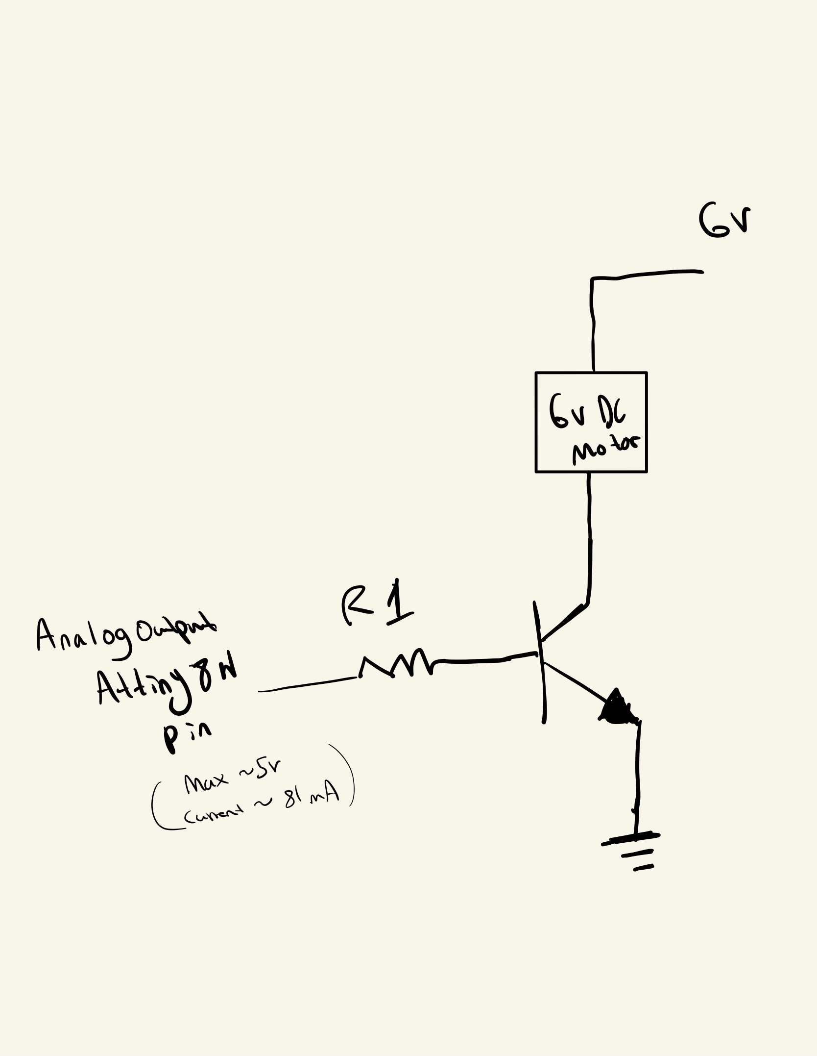
Thanks in advance! : )

\$\endgroup\$

1 Answer 1

2
\$\begingroup\$

There are no specifications of operating current for that motor, but a similar motor has an idle current of 280 mA, and a max efficiency current of 1.6 amps. At 6V, that is more than 9W. The 2N2222 transistor can handle a maximum of 600mA but maximum power dissipation without heatsink is about 1/2 W.

The best way to control this motor would be using PWM, and the transistor would need to be driven in saturation so that it will have only about 200 mV when turned on. To get 600 mA, you would need about 50 mA base current, which (I think) is more than the ATtiny can safely provide. And the transistor would be at its maximum with 600 mA. It might work, but much better would be a MOSFET, or at least a power transistor, probably a Darlington.

As for calculating the base resistor, you need to use the difference between the drive voltage (5V) and the base-emitter voltage (0.7V), so for 50 mA that would be 4.3/0.05 = 86 ohms. I think the ATtiny analog output is PWM, so you would need this resistor for the ON time of the duty cycle.

BTW, don't forget to add a commutating (flyback or freewheeling) diode across the motor to take care of inductive kick-back.

\$\endgroup\$
2
  • \$\begingroup\$ Thanks for the detailed answer! So I could use this transistor, but as you state if I do so, it'll quickly overheat which is not ideal in small enclosed spaces right? Moreover, if I choose, let's say a MOSFET for example, then would the base-emitter voltage be different? Thanks for the answer nonetheless! : ) \$\endgroup\$
    – A Friend
    Commented Jan 8, 2023 at 2:50
  • \$\begingroup\$ A MOSFET has an insulated gate, which requires a minimum voltage to turn on, like a switch. You would want a logic level device like IRLZ44. digikey.com/en/products/detail/vishay-siliconix/IRLZ44PBF/… or IRL520 digikey.com/en/products/detail/infineon-technologies/IRL520NPBF/… \$\endgroup\$
    – PStechPaul
    Commented Jan 8, 2023 at 3:55

Your Answer

By clicking “Post Your Answer”, you agree to our terms of service and acknowledge you have read our privacy policy.

Not the answer you're looking for? Browse other questions tagged or ask your own question.