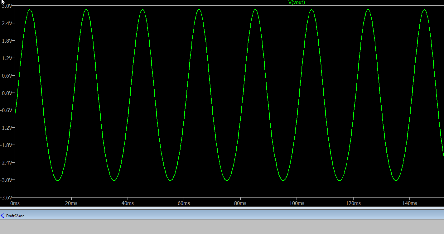
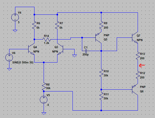
I would suggest using real transistor models for this. If I do that, and adjust R8 to get approximate balance at 0V in (open-loop) I can get nice gain (2.5mV in, R8 = 19.5kΩ, transistors 2N4401/4403, otherwise same as your circuit) :

Here is the .asc file:
    Version 4
SHEET 1 1156 680
WIRE 160 -144 -96 -144
WIRE 352 -144 160 -144
WIRE 720 -144 352 -144
WIRE 992 -144 720 -144
WIRE 720 -112 720 -144
WIRE -96 -96 -96 -144
WIRE 992 -96 992 -144
WIRE 160 -80 160 -144
WIRE 352 -80 352 -144
WIRE 928 -48 848 -48
WIRE 720 0 720 -32
WIRE 160 48 160 0
WIRE 592 48 160 48
WIRE 656 48 592 48
WIRE 992 48 992 0
WIRE 160 96 160 48
WIRE 352 96 352 0
WIRE 96 144 -32 144
WIRE 448 144 416 144
WIRE 592 160 592 48
WIRE 720 160 720 96
WIRE 720 160 656 160
WIRE 992 160 992 128
WIRE 1088 160 1088 144
WIRE 1088 160 992 160
WIRE 1152 160 1088 160
WIRE -32 192 -32 144
WIRE 992 192 992 160
WIRE 448 208 448 144
WIRE 720 208 720 160
WIRE 848 208 848 -48
WIRE 848 208 720 208
WIRE 160 240 160 192
WIRE 256 240 160 240
WIRE 352 240 352 192
WIRE 352 240 256 240
WIRE 720 256 720 208
WIRE 256 288 256 240
WIRE 992 352 992 272
WIRE 256 384 256 368
WIRE 528 384 256 384
WIRE 720 400 720 336
WIRE 928 400 720 400
WIRE 256 416 256 384
WIRE 720 432 720 400
WIRE 528 544 528 384
WIRE 720 544 720 512
WIRE 720 544 528 544
WIRE 992 544 992 448
WIRE 992 544 720 544
FLAG 256 496 0
FLAG -96 -16 0
FLAG -32 272 0
FLAG 1088 144 Vout
FLAG 448 208 0
SYMBOL npn 96 96 R0
SYMATTR InstName Q1
SYMATTR Value 2N4401
SYMBOL npn 416 96 M0
SYMATTR InstName Q2
SYMATTR Value 2N4401
SYMBOL res 240 272 R0
SYMATTR InstName R1
SYMATTR Value 19.5k
SYMBOL voltage 256 400 R0
WINDOW 123 0 0 Left 0
WINDOW 39 0 0 Left 0
SYMATTR InstName V1
SYMATTR Value -5
SYMBOL res 144 -96 R0
SYMATTR InstName R2
SYMATTR Value 6k
SYMBOL voltage -96 -112 R0
WINDOW 123 0 0 Left 0
WINDOW 39 0 0 Left 0
SYMATTR InstName V2
SYMATTR Value 5
SYMBOL res 336 -96 R0
SYMATTR InstName R3
SYMATTR Value 6k
SYMBOL voltage -32 176 R0
WINDOW 123 0 0 Left 0
WINDOW 39 0 0 Left 0
SYMATTR InstName V3
SYMATTR Value SINE(0 2.5m 50)
SYMBOL pnp 656 96 M180
SYMATTR InstName Q3
SYMATTR Value 2N4403
SYMBOL res 704 -128 R0
SYMATTR InstName R4
SYMATTR Value 200
SYMBOL cap 656 144 R90
WINDOW 0 0 32 VBottom 2
WINDOW 3 32 32 VTop 2
SYMATTR InstName C1
SYMATTR Value 200p
SYMBOL res 704 240 R0
SYMATTR InstName R5
SYMATTR Value 30k
SYMBOL res 704 416 R0
SYMATTR InstName R6
SYMATTR Value 50k
SYMBOL pnp 928 448 M180
SYMATTR InstName Q4
SYMATTR Value 2N4403
SYMBOL npn 928 -96 R0
SYMATTR InstName Q5
SYMATTR Value 2N4401
SYMBOL res 976 32 R0
SYMATTR InstName R7
SYMATTR Value 200
SYMBOL res 976 176 R0
SYMATTR InstName R8
SYMATTR Value 200
TEXT -130 554 Left 2 !.tran 200m
In a closed-loop circuit, with a high-gain op-amp, the offset will translate to a rather small input offset but this at least allows the theoretical behavior to be observed open-loop.


