2
\$\begingroup\$

I am considering a classic power distribution network using 3-phase AC power. There is usually power lines of various voltages ranging from 10kV to 400kV. These values change country-by-country. For example in France, the distribution network is usually of 20kV, and the transmission network is made of 63kV, 90kV, 225kV and 400kV lines.

I wonder the relationship between the power line's voltage and the amount of power it can carry. For example, I wonder how many 200kV lines would make the same job as a single 400kV line.

Arguments towards a linear relationship : P = U*I so assuming the same current, by doubling the powerline voltage, we double the amount of power transmitted.

Arguments towards a quadratic relationship : A powerline designed with twice the voltage has everything larger, higher pylons, thicker conductors. Therefore a line designed with twice the voltage can have its current that can go through the cables double as well. Thus a line with 2x the voltage will carry 4 times more power.

Arguments towards a cubic relationship : If the wires of a power line for twice the voltage have their diameter twice larger, it means their surface is 4 times as much, thus supporting 4 times the current, hence 8 times the power.

\$\endgroup\$
5
  • \$\begingroup\$ I would expect the power company to increase U and I at similar rates, because that probably optimizes the building cost compared to the amount of power \$\endgroup\$ Commented Feb 15, 2023 at 14:42
  • 1
    \$\begingroup\$ Think about designing for constant efficiency - power reaching the end divided by power sent in at the start, the difference between those two being lost as I2R losses. Or capital cost efficincy, power delivered per dollars of material cost. \$\endgroup\$
    – Neil_UK
    Commented Feb 15, 2023 at 14:54
  • 1
    \$\begingroup\$ #1. There is some truth to #2 and #3, but you have made overreaching assumptions. \$\endgroup\$
    – Mattman944
    Commented Feb 15, 2023 at 15:01
  • \$\begingroup\$ The ONLY reason to increase the voltage, is to minimise the IR losses for a given distance and for a given defined maximum power load requirement. Reducing current also allows thinner conductors, 'weaker' pylons etc, but conversely also requires higher pylons & more insulation. So its a complex balancing act. \$\endgroup\$ Commented Feb 15, 2023 at 15:01
  • \$\begingroup\$ Higher voltage power lines don't use thicker conductors. Higher current lines use thicker conductors. \$\endgroup\$
    – Hearth
    Commented Feb 15, 2023 at 15:35

2 Answers 2

2
\$\begingroup\$

There are a lot of factors at play in the increase of the capacity of overhead transmission lines as the nominal system voltage increases. By "capacity", I mean the thermal limit based on heating of the conductors and subsequent increasing in the sag.

  • Power transferred is proportional to voltage
  • Due to the way impedance reflects through transformers, higher voltage lines have lower "per-unit" impedance even for the same physical construction. This effect goes with the square of voltage. This does not change the current-carrying capacity of the line, but it does mean that in a networked system, the higher voltage lines will tend to carry more load, and therefore will be designed with greater capacity.
  • Due to corona effects, high voltage lines (approximately 230 kV and above) are designed with minimum conductor sizes and utilize bundled conductors to reduce the electric field gradient around the conductors and reduce the inductive reactance of the line
  • At the highest voltages, cost of terminal equipment at substations is relatively higher, and lines tend to be very long, so the load that the line is able to carry tends to be limited by system stability concerns and the inductive reactance of the line rather than the thermal limits of the line. This means there is less incentive to keep increasing thermal limits.

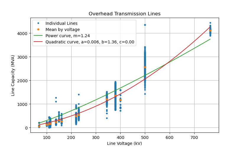
I do not currently have access to any utility's line rating database, but I did pull together some publicly available transmission system models that are based on real utility data. Below is a plot of the empirical relationship between system nominal voltage and transmission line capacity. Figure of system nominal voltage vs transmission line capacity

I fit a power curve and a quadratic curve (with y-intercept fixed at 0) to the mean points at each voltage level. For a power relationship, the best overall fit is a power of 1.24. In relation to your original question, it shows the relationship is between linear and quadratic.

The quadratic curve is a better fit to the data, but its hard to relate it to your original question.

Unfortunately, I do not have handy access to similar data for lower voltage systems, so I'm not able to include distribution-level line designs.

Here's my source code to do the analysis and generate the plot.

\$\endgroup\$
4
\$\begingroup\$

Arguments towards a quadratic relationship : A powerline designed with twice the voltage has everything larger, higher pylons, thicker conductors.

Making the conductors thicker is not necessary to design for higher voltage. (Making the insulators thicker, is required)

If you make the conductors thicker then you are changing the design to allow for higher current.

If you design for both higher voltage and higher current, then yes, the power carrying capability will increase more than if you just design for higher voltage.

As the designer you have the freedom to do this in any proportion, you don't have to double the current if you double the voltage. You could even design for lower current at higher voltage, keeping the power the same (for example, this might save you on the cost of the wires).

If you're talking about cross-country transmission lines you might be constrained by things like the weight-bearing capacity of the pylons, wind loading, etc.

Arguments towards a cubic relationship : If the wires of a power line for twice the voltage have their diameter twice larger, it means their surface is 4 times as much, thus supporting 4 times the current, hence 8 times the power.

It's not the total surface area, but the surface area per unit length, (aka, the circumference) that matters. And the circumference only increases in proportion to the diameter, not as the square of the diameter.

\$\endgroup\$
6
  • \$\begingroup\$ At high transmission voltage levels, about 230 kV and above, the conductor size is increased with voltage to reduce corona effects. Either larger conductors are used and/or each phase's conductors are bundled with spacers between them. \$\endgroup\$
    – pdb5627
    Commented Feb 16, 2023 at 8:55
  • \$\begingroup\$ "It's not the total surface area, but the surface area per unit length". Circumference may be a factor in that it affects the rate that the conductor dissipates heat, but the bigger factor is the resistive losses in the conductor that generate the heat. Resistive losses will be generally proportional to the inverse of conductor diameter squared, although at transmission-level voltages, the core of the conductor (e.g. steel) is used for strength rather than conducting current flow, so it's not quite that simple. \$\endgroup\$
    – pdb5627
    Commented Feb 16, 2023 at 9:14
  • 1
    \$\begingroup\$ @pdb5627, the issue is skin depth. Even at 60 Hz, the skin depth is only a few mm. So if the conductor radius is bigger than that the circumference of the conductor is more important than the cross-section area in determining the resistance. (And this is why they can use steel cores without affecting the resistance much) \$\endgroup\$
    – The Photon
    Commented Feb 16, 2023 at 22:15
  • \$\begingroup\$ According to the Aluminum Electrical Conductor Handbook, the ratio of ac resistance to dc resistance (Rac/Rdc) ranges from near 1.0 for small conductors to 1.09 for 1590 kcmil all-aluminum conductors. So skin effect is a factor, but not enough to change the relationship of resistance from inverse of square of diameter to inverse of diameter.To see the relationship with conductor ampacity, I reference the Southwire specifications for ACSR. At the small end, 6 AWG (diameter = 0.198 in) is 105 A, while at the upper end, 2167 kcmil "Kiwi" (diameter = 1.735 in) is 1607 A. \$\endgroup\$
    – pdb5627
    Commented Feb 17, 2023 at 7:07
  • \$\begingroup\$ Using a table of conductor specifications for ACSR from Southwire, the power of the relationship from 6 AWG "Turkey" to 2167 kcmil "Kiwi" is calculated as log(0.0106/0.806) / log(1.735/0.198) = -2.00. The power of the relationship to ampacity, on the other hand, is calculated as log(1607/105) / log(1.735/0.198) = 1.26. This is more than linear but much less than a power of 2. \$\endgroup\$
    – pdb5627
    Commented Feb 17, 2023 at 7:15

Your Answer

By clicking “Post Your Answer”, you agree to our terms of service and acknowledge you have read our privacy policy.

Not the answer you're looking for? Browse other questions tagged or ask your own question.