2
\$\begingroup\$

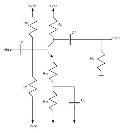
I am trying to design a BJT amplifier with the given parameters and limitations. The circuit is shown below.

enter image description here

Parameters:

  • Vcc = 15 V
  • RL = 20 kΩ
  • beta = 180
  • Vbe(on)= 0.6 V
  • Cµ = Cπ = 0

Limitations are:

  1. Swing voltage of Vout must be between 22 and 24 V (peak to peak)
  2. Voltage gain must be more than 10
  3. Power dissipation by resistors must be under 0.2 W
  4. Corner frequencies of C1, C2, and CE should be < 10 Hz
  5. The high threshold frequency should be 20 kHz

I assumed that Rc must be smaller than RL so I designed Rc= 2 k ohms and then I found RE1 = 180 ohms, but I have an issue where I have to design RE2. I don't know how to use 22-24 V pk-pk specification in this design.

  • How do I adjust peak to peak voltage?
  • How can I calculate input and output impedances and open circuit voltage gain?
  • How do I approach power dissipation considerations?

As it's a homework question, I'm not looking for a whole solution, but some tips and advice.

\$\endgroup\$
15
  • 1
    \$\begingroup\$ Because it is homework you need to show some effort at solving this to give an indication as to where you are stuck. \$\endgroup\$
    – Andy aka
    Commented Mar 4, 2023 at 15:08
  • \$\begingroup\$ ...begin? perhaps trying Rc smaller than RL. Then work out resistors to satisfy DC bias in the transistor's linear region. Expect to refine your initial choice of resistor values later when other specs are difficult to attain. 24V pk-pk spec will be the first one I'd try to achieve. Perhaps it is assumed to be a linear amplifier, but no mention of this is made, a "cheat" might allow a non-linear amplifier (which is a bit easier to design) - however the gain spec of ten is at risk of violation. \$\endgroup\$
    – glen_geek
    Commented Mar 4, 2023 at 15:23
  • 1
    \$\begingroup\$ What background do you have in this problem -- what has been covered in class so far, by the instructor, handouts, textbook? What BJT circuits have you analyzed so far? What level of analysis are you comfortable with (DC or AC steady state, dependent sources, nodal analysis, etc.)? \$\endgroup\$ Commented Mar 4, 2023 at 15:27
  • 1
    \$\begingroup\$ Also to clarify, +/-Vcc is symmetrical, so the total supply is 30V? \$\endgroup\$ Commented Mar 4, 2023 at 17:54
  • 1
    \$\begingroup\$ @Aldocest Have you disappeared from the world? Or still interested in the topic? \$\endgroup\$ Commented Oct 26, 2023 at 4:40

1 Answer 1

1
\$\begingroup\$

Just some of my initial thoughts. Perhaps they may help:

  • Your specifications appear to hold a fixed \$V_{_\text{BE}}\$ value. This never happens, in practice. In fact, \$V_{_\text{BE}}\$ is continually changing with the applied signal and will distort the output and complicate (somewhat) the situation with such a tight peak-to-peak limitation range. But as luck would have it, you don't need to care about this reality. Nice. This means that you don't have to deal with \$r_e^{\,'}\$ as there's no dynamic resistance, which leads into the next note:
  • For purposes of arranging the specified loaded voltage gain of \$A_v=10\$, you treat the collector resistor as being in parallel with the load. So, this means your goal is to have \$\frac{R_{_\text{C}}\,\mid\mid\,R_{_\text{L}}}{R_{_{\text{E}_{1}}}}=A_v\$.
  • I'd select \$23\:\text{V}_{_\text{PP}}\$ (roughly) to allow some margin and I'd constrain the loaded gain to just slightly more than the allowed 10. So the required input will be \$2\frac14\:\text{V}_{_\text{PP}}\$ and the loaded voltage gain will be taken as \$A_v\approx 10.2\$.
  • \$C_{_\text{E}}\$ will be taken to be large enough that its voltage remains fixed.

The power constraint may prevent success. The smaller you make \$R_{_\text{C}}\$ the closer the collector swing is to the specified swing on the load and this helps better fit it within the rails. But it increases the quiescent current required. And that is something that cannot be easily afforded. And if you focus on keeping the power manageable by reducing the quiescent current and increasing \$R_{_\text{C}}\$, the circuit must handle an ever-increasing collector swing. And that is also something that cannot be easily afforded. I've not spent enough time on this and I may have made a mistake, but a back-of-envelope calc suggests some worry.

\$\endgroup\$

Your Answer

By clicking “Post Your Answer”, you agree to our terms of service and acknowledge you have read our privacy policy.

Not the answer you're looking for? Browse other questions tagged or ask your own question.