2
\$\begingroup\$

We can use coupled LC circuit to understand the normal modes of coupled oscillators of a lattice.
We are using this to get the dispersion relation of the angular frequency for the oscillation.

Background
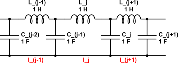
schematic

simulate this circuit – Schematic created using CircuitLab

Suppose we have N coupled LC oscillators. In the above diagram, we assume in the loops the current is flowing in counter clockwise direction and the upper plate of the capacitor is positively charged and lower plate is negatively chaged.
KVL equation for the \$j-th\$ loop is
\$L\frac{dI_j}{dt}=-\frac{q_j}{C}+\frac{q_{j-1}}{C}\tag{1}\$
As, \$\frac{dq_j}{dt}=I_j-I_{j+1}\$ and \$\frac{dq_{j-1}}{dt}=I_{j-1}-I_j\$
Differentiating \$(1)\$ with \$t\$, we get
\$L\frac{d^2I_j}{dt^2}=-\frac{I_j-I_{j+1}}{C}+\frac{I_{j-1}-I_j}{C}\tag{2}\$
\$\implies \frac{d^2I_j}{dt^2}=-(-\omega_o^2I_{j-1}+2\omega_o^2I_j-\omega_o^2I_{j+1})\tag{3}\$

If we can consider infinite number of coupled oscillators then the matrix associated with the equation will become circulant and the Fourier transform matrix can diagonalize it. But in that case all the frequencies will be allowed.
To get back the case of n-coupled oscillators from infinite oscillators, we have to impose the boundary condition that \$I_o=I_{N+1}=0\$. This leads to the restriction on the oscillation frequency.
We will get the following result,
\$I_{j,m}=\mathbb{Re}(\Big(\sin\Big(j\frac{m\pi}{N+1}\Big)e^{i\omega_mt}\Big)\tag{4}\$
\$\omega_m^2=\frac{2}{LC}\Big(1-\cos\big(\frac{m\pi}{N+1}\big)\Big)=\frac{2}{LC}\Big(1-\cos\theta_m\Big)\tag{5}\$
where \$m=1,2,...,N\$ are the N normal modes of the oscillators.
Some normal modes for \$N=4\$
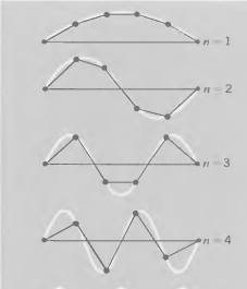
enter image description here

On y-axis is current and x-axis is position of the each oscillator.
We can see that for each circuit current becomes maximum at the same time, so the phase difference between any can be either \$0\$ or \$\pi\$.
This analysis is clear to me.

Experiment
In the experiment, we have a kit in which we can change the frequency of input voltage to the N coupled LC oscillator. The output of the kit is connected to the oscilloscope (operated in XY mode). In oscilloscope, we get Lissajous figure (which gives the phase difference between the input and output voltage).
In manual it is written that

The transmission line consists of ten sections and it is excited by constant source (audio oscillator is series with resistance R1). To eliminate the reflected wave and thus to simulate an infinite line, the line should be terminated by the resistance equal in valve to the characterisitc impedance \$\sqrt{L/C}\$.

So, we are recording phase difference between input and output signal (of the multiples of \$90^o\$) in the oscilloscope for the associated input frequency.

Doubts

(i) When we plot frequency as a function of phase difference between and output voltage then we found that it satisfies \$(5)\$ and by fitting it we get the value for \$LC\$ to a good accuracy. I am not able to understand how this phase difference corresponds to the angle given in \$(5)\$. Basically the input signal excites the normal mode when its frequency is equal to the normal mode frequency. The \$\theta_m\$ is the characteristic of the normal mode. But can somebody explain how the angle \$\theta_m\$ in the \$(5)\$, corresponds to the phase difference between input and output signal? And how it is always the multiple of \$90^o\$?

(ii) I am not able to understand the logic behind using \$R_2\$. It has been said that we have to make \$R_2=\sqrt{L/C}\$, to eliminate reflected wave and simulate infinite line. I am not able to understand what does it mean.

I am a physics student, I am familiar with the basic high school electronics, so please explain accordingly.

\$\endgroup\$
11
  • 2
    \$\begingroup\$ I see no oscillators in your circuits. Why did capacitance change from 1 uF to 1 farad halfway through your pi filters? Why did inductance change from 1 henry to 1 uH too? \$\endgroup\$
    – Andy aka
    Commented Mar 20, 2023 at 9:41
  • 1
    \$\begingroup\$ There are at least ten places where you have used the word oscillator plus a tag. I'm sure that most of them are still in error. \$\endgroup\$
    – Andy aka
    Commented Mar 20, 2023 at 11:51
  • 1
    \$\begingroup\$ In mechanics, we have n coupled spring mass system. We know that each spring mass system is analogous to a series LC circuit because of the same nature of differential equation of the both. Now to analyze the n coupled spring mass system is somewhat difficult from designing the experiment point of view but we can easily make a coupled LC circuit to analyze the behaviour of the coupled oscillator. \$\endgroup\$
    – Iti
    Commented Mar 20, 2023 at 11:58
  • 1
    \$\begingroup\$ @Andyaka "oscillators" in the physics sense i.e. SHO, not an active circuit. I guess I don't know whether EE.SE makes (or should make) the more specific distinction. Iti: repeat the analysis but with \$I_o\$ satisfied by the resistor (I = Vo/R), or additionally driven by the source (\$I_o = \frac{V_{in} - V_o}{R}\$ where Vo is some function of time) to get the inhomogeneous solution. \$\endgroup\$ Commented Mar 20, 2023 at 12:01
  • 3
    \$\begingroup\$ Semantics seems to be a touchy point here. Personally, I'd be a bit happier to see the word " resonator " substituted for " oscillator ". \$\endgroup\$
    – glen_geek
    Commented Mar 20, 2023 at 13:55

2 Answers 2

2
+50
\$\begingroup\$

How it is always the multiple of 90 °?

If each LC section is resonating then, each section naturally introduces a phase shift of 90 ° at resonance. This can be proven very easily and, if needed I will add that proof.

So, if you do the algebra on a simple LC low-pass filter (a single stage) then, as frequency increases from DC, the phase angle between input and output starts at 0 ° then, as resonance approaches, the phase shifts dramatically and becomes exactly 90 ° at the LC natural resonance. If frequency increases a little past resonance then the phase angle rapidly becomes 180 ° and remains at that phase angle for all higher frequencies.

It has been said that we have to make \$R_2=\sqrt{L/C}\$, to eliminate reflected wave and simulate infinite line. I am not able to understand what does it mean.

I believe that your reference to R2 means it is added to the output of the stage furthest away from the driving source so, then it becomes basic transmission line theory.

I've shown the algebra in an appendix if you need it but, suffice to say that the characteristic impedance of a lossless cable is found by stringing together an infinite number of LC low-pass stages (just as you have in your question's picture).

So, the problem in your question is "borrowing" standard transmission line theory to find the input impedance of the coupled line and, the important thing to note is that if the line is not infinite in length, it can be terminated by a resistor of a certain value to prevent reflections from the final stage. That impedance is \$\sqrt{\frac{L}{C}}\$.


Appendix - characteristic impedance

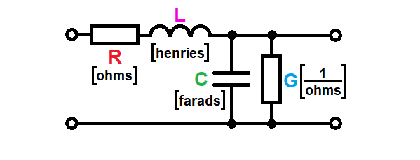
To find \$Z_0\$ start with a representation of a short section of transmission line (t-line): -

enter image description here

R, L, C and G can be thought of as "per metre" values but, as will be suggested further down, they can be based on "per mm" or per micron all the way to zero length.

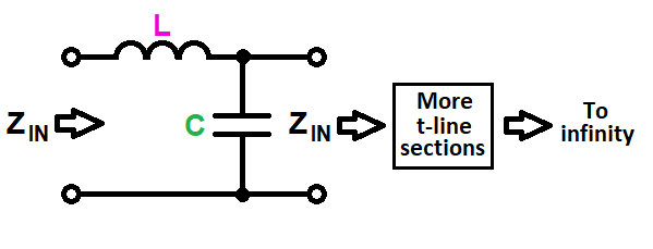
The model in your question uses only L and C hence, the section becomes this: -

enter image description here

The section has an input impedance \$Z_{IN}\$ on the left that we want to find. On the right, more sections are connected. They all have the same input impedance.

We can now solve for \$Z_{IN}\$ on the left: - $$$$ $$Z_{IN}\hspace{0.5cm} =\hspace{0.5cm} sL + \dfrac{1}{sC}||Z_{IN}\hspace{0.5cm} =\hspace{0.5cm} sL + \dfrac{Z_{IN}}{1 +sC Z_{IN}} $$

$$Z_{IN}\cdot (1 + sCZ_{IN})\hspace{0.5cm} =\hspace{0.5cm}sL + s^2LCZ_{IN} + Z_{IN}$$

$$sCZ_{IN}^2\hspace{0.5cm} =\hspace{0.5cm} sL + s^2LCZ_{IN} $$

$$Z_{IN}^2 \hspace{0.5cm}=\hspace{0.5cm}\dfrac{L}{C} + sL Z_{IN}$$

That looks about as far as it goes but, if we imagine our section of t-line shrunk towards zero length, \$sL\cdot Z_{IN}\$ becomes insignificant compared to \$\frac{L}{C}\$ hence: -

$$Z_{IN} = \sqrt{\dfrac{L}{C}}$$

T-line images stolen from one of my earlier answers.

\$\endgroup\$
0
\$\begingroup\$

Are you trying to build a transmission line oscillator? That is my guess anyhow. The L-C sections that you show, assuming they are of the same value can implement a lumped approximation to a transmission line. The big clue is your mentioning sqrt(L/C) = R2 (I assume it's a resistor at the end). That's the expression for the characteristic impedance of a transmission line. In the lumped case the L's and C's represent the inductance and capacitance over some distance, and the number of sections make the line "longer". The transmission line can be used as a quarter wave transformer at the appropriate frequency to translate a capacitor into an apparent inductance, for example, so as to implement an inductor-less oscillator (except for all the ones in the line, of course).

\$\endgroup\$
1
  • \$\begingroup\$ He is using the LC network to simulate a one-dimensional lattice of atoms: point like masses coupled by springs. The equations of motion, and the relation dispersion (which imo misses a square) are the same for both systems. The analysis of this system can be found for example on Crawford, "Berkeley Physics vol 3 - Waves". The dispersion relation w = w(k) does not depends on the number of atoms or LC stages, and k can be linked to the phase angle he is.measuring after N stages. It might require some math to show it, but since this question will probably be closed due to semantics... \$\endgroup\$ Commented Mar 25, 2023 at 1:58

Your Answer

By clicking “Post Your Answer”, you agree to our terms of service and acknowledge you have read our privacy policy.

Not the answer you're looking for? Browse other questions tagged or ask your own question.