4
\$\begingroup\$

I designed a PCB with several modules. Relevant for this question are:

  • MCU (STM32L476ZGT3)
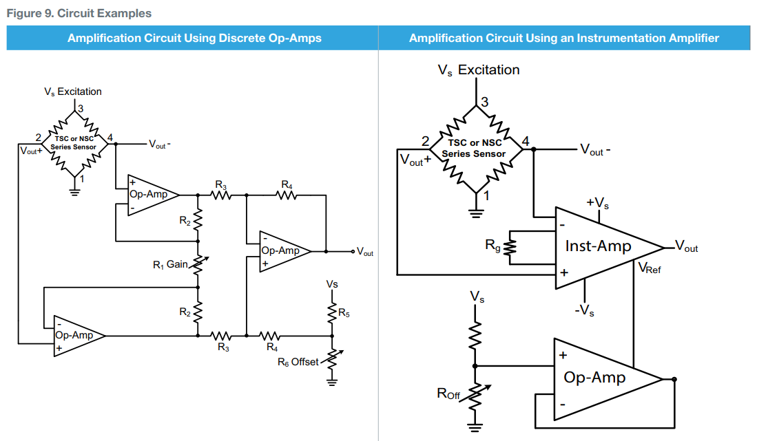
  • 2 analog pressure sensors in the following configuration enter image description here

RG has 0.1% tolerance. As you see in the figure, there are 4 points where I read with the internal ADC on the MCU - actually the forth is not used. Reason for that was to compare noise.

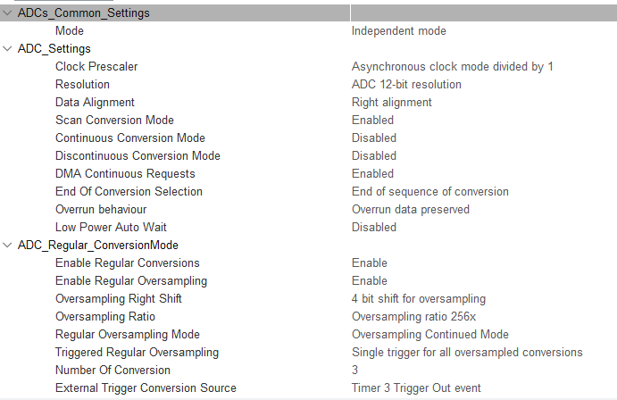
I set the ADC in this way: enter image description here

I can read from the ADC with no issues. The problem is what I read. The sensors are bidirectional, so I expect to read something close to the half of the ADC max value (= 65520) when no pressure is applied.

Instead what I read is the following:

-sensor 1-
ADC_PS1 = 33373
ADC_PS1_2 = 31738
ADC_PS1_3 = 30767

-sensor 2-
ADC_PS2 = 33196
ADC_PS2_2 = 31280
ADC_PS2_3 = 30499

I have 2 questions:

  1. Why there is always some difference among the two sensors, for example between ADC_PS1 and ADC_PS2? Shouldn't they be pretty much the same?
  2. Why ADC_PS2, ADC_PS2_2, and ADC_PS2_3 are so different? Same is for the other sensor.

All signals are clean with negligible noise.
Thank you all!

\$\endgroup\$
5
  • \$\begingroup\$ Your table shows a 12 bit ADC yet you say you use a 16 bit type. \$\endgroup\$
    – Andy aka
    Commented Apr 4, 2023 at 17:04
  • \$\begingroup\$ The most likely reason to get a different ADC reading would be that the analog voltage is different - did you check it? \$\endgroup\$ Commented Apr 4, 2023 at 17:35
  • 1
    \$\begingroup\$ ADC_PS1 and ADC_PS2 are pretty much the same. The difference is about 0.01 volts. \$\endgroup\$ Commented Apr 4, 2023 at 17:35
  • \$\begingroup\$ @Andyaka I use 16 bit because I oversample, as it is shown in the ADC configuration. \$\endgroup\$
    – mdir
    Commented Apr 5, 2023 at 7:16
  • \$\begingroup\$ @user253751 the analog voltage is the same \$\endgroup\$
    – mdir
    Commented Apr 5, 2023 at 7:33

2 Answers 2

7
\$\begingroup\$

Your error budget needs to account for the following: ADC_PS1 is off 1.8%; ADC_PS2 has an error of 1.3% from theoretical.

  • AD623BRZ has an input offset voltage up to 100uV. With a gain of 62, this is 6.2 mv, or about 1.8% worst case.
  • Transducer full scale range is 10.5 mV/V. Offset is +/- 0.075mV/V, or 0.7%FS.
  • MCU (STM32L476ZGT3) advertises only 5 LSB total error (0.1%). However, it has analog input resistance of up to 50K, depending on sampling rate. Only ADC_PS1 and ADC_PS2 have a low enough impedance to keep this from factoring in. Each of your other two sampling points has a high impedance, and each has a different impedance.

Your circuit seems to be operating within its design specs.

\$\endgroup\$
4
  • \$\begingroup\$ Hi, thank you for your answer! What would you do for improving the error budget? I am also open to replace the amplifier. \$\endgroup\$
    – mdir
    Commented Apr 5, 2023 at 8:04
  • \$\begingroup\$ First, only use the low impedance signal. I would put an offset adjustment into your firmware. \$\endgroup\$ Commented Apr 5, 2023 at 13:17
  • \$\begingroup\$ I see. There is a point in your answer still not clear to me. Should be ADC_PS1(2)_3 low impedance too since that is the output of an amplifier? \$\endgroup\$
    – mdir
    Commented Apr 5, 2023 at 15:25
  • \$\begingroup\$ It is low impedance but the input has already been degraded \$\endgroup\$ Commented Apr 5, 2023 at 19:01
3
\$\begingroup\$

Are you sure the sensor is wired correctly?

The Honeywell TSCDRRN015PDUCV datasheet shows the following reference circuit, where 1 and 3 are power and 2 and 4 are signal:

TSCDRRN015PDUCV Datasheet

No further details about construction are given, so we cannot determine if all of the resistor elements are supposed to be equal or not. But if it is supposed to have millivolts output, my guess is that they are not equal, and wiring it incorrectly will not work (and lead to output values saturated at power rails.)

Note that these also seem particularly sensitive to soldering heat: Lead solder temperature (SIP, DIP) 4 s max. at 250 °C [482 °F] That is quite low; special low-temperature solder may be required.

\$\endgroup\$
1
  • \$\begingroup\$ thank you for you reply. Actually this was a mistake on the PCB and therefore I had to use some short wires on the PCB. To reply to you second question, I haven't soldered the sensors at all because I used some connectors into which to place them. \$\endgroup\$
    – mdir
    Commented Apr 5, 2023 at 7:48

Your Answer

By clicking “Post Your Answer”, you agree to our terms of service and acknowledge you have read our privacy policy.

Not the answer you're looking for? Browse other questions tagged or ask your own question.