When the switch is off, the magnetic field collapses and is
transferred as energy into the secondary.
Let me start here: the magnetic field doesn't collapse when the switch turns off; the magnetic field ramps-down in a controlled manner and, so does the current in the secondary. So, the magnetic field ramps-down to zero (discontinuous conduction mode) and the secondary current also ramps-down to zero in exactly the same time period. Importantly, the rate at which the secondary current decays dictates the secondary voltage produced (more below on this).
What I fail to understand is the relationship between voltage and
current at the output: is it correct to consider the flyback a
"current source?"
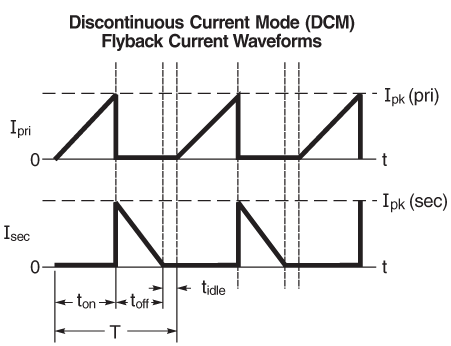
Here's where your misunderstanding likely occurs. As mentioned above, the magnetic field and current ramp-down to zero and, the rate at which the current ramps-down \$\left(\frac{di}{dt}\right)\$ multiplied the secondary inductance, equals the secondary output voltage. Below are input and output current waveforms when the primary and secondary inductances are equal i.e. a 1:1 transformer: -

The slopes follow the basic inductor equation: \$V = L\frac{di}{dt}\$
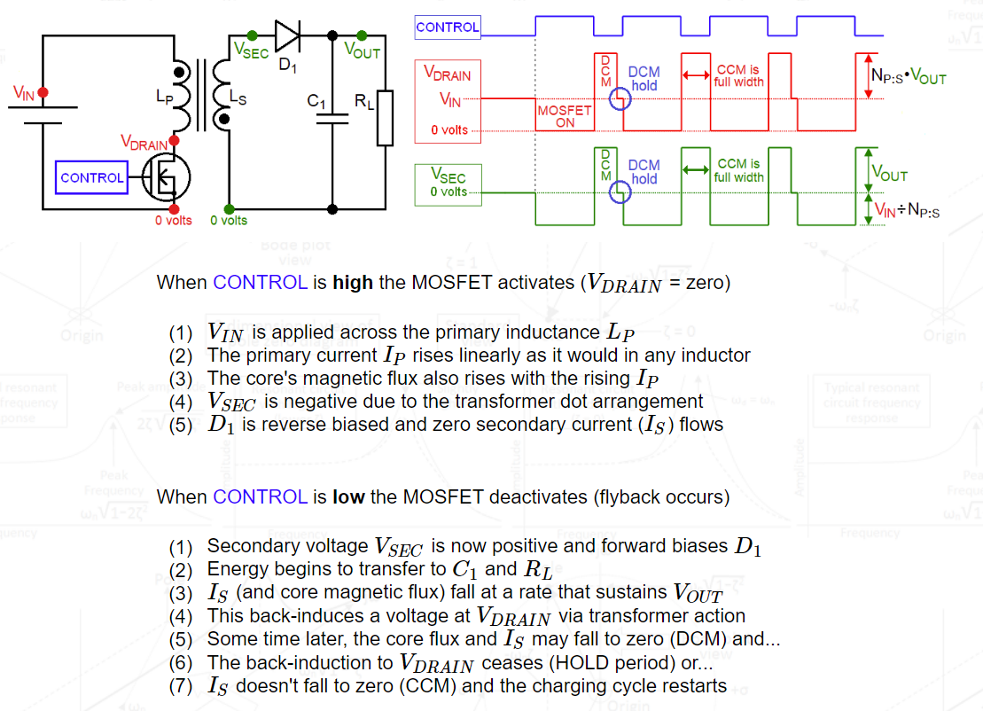
Image from this answer. Maybe this mini-explanation from my basic website will also help you understand the voltages produced: -

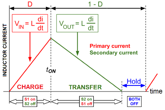
Below is another image of the currents seen during charging (red) and transfer (green). The waveforms begin with the output capacitor fully discharged and gradually move through to the right where the output capacitor is charged to a voltage that is three times the input supply voltage: -

- The green-line slope is zero on the left during the 1st cycle meaning that Vout starts at zero
- It's slope increases during that elongated first cycle meaning that Vout rises
- In the 2nd cycle, the green-line slope equals the slope at the end of the first cycle
- This is because Vout restarts at the same voltage when it stopped in the previous cycle
- This repeats for every subsequent cycle
- As the charge and transfer cycles progress the change in slope becomes less evident
- This is because the change in capacitor voltage becomes less as time progresses
- Notice that a flat blue line appears indicating that the conversion has dropped into DCM
- Eventually the slope of the green line is three times the slope of the red line
- This means that the output voltage is three times the input voltage
- If I drew more cycles the green line slope would become greater
What is the relationship between the transformer turns ratio and the
output voltage and current? I read people claiming that I should not be
able to achieve 1.5 kV with a 10 turn ratio transformer with a 5 V DC
input, but I have seen applications and schematics where an 8 turn
ratio transformer is capable of charging a 2 kV capacitor, albeit
slowly
Let's work through an example. Your turns ratio (\$N_{P:S}\$) is 1:10 and, when fully charged, the output capacitor voltage is 1500 volts. When the secondary is producing 1500 volts, the primary (now disconnected by the switch) receives a flyback voltage from the secondary.
This next bit is important to understand
In the "transfer" part of the switching cycle, the primary and secondary roles are reversed and, the primary receives an induced voltage of:
1500 volts ÷ 10 (turns ratio) = 150 volts.
This happens because the primary is disconnected (the MOSFET switch is open) and the secondary has 1500 volts. It doesn't matter that the secondary is generating 1500 volts or receiving 1500 volts from an external source; transformer action still takes place.
Now that isn't quite the full story because the voltage seen on the switch (assumed to be the drain of a MOSFET) is 155 volts. This is because you have a 5 volt DC supply.
If your MOSFET can handle a peak drain voltage of more than 155 volts then you could be in business. But, let's not forget that the primary to secondary coupling is never 100% and there will be another glitch on top of the 155 volts that you should try and quench with some form of snubber or clamp. A 250 volt MOSFET should do the job just nicely.
But, if you decided that a 1:100 step up transformer is your choice, the flyback voltage from the secondary is only 15 volts. Add this to the supply of 5 volts and, add another 10 or 20 volts for the back-emf due to non-ideal coupling and, the MOSFET drain will see about 30 to 40 volts.
In other words, the choice of transformer can make the choice of MOSFET simpler.
Of interest might be the fact that I'm designing a 50 kV capacitor charging supply but I can't supply details unfortunately.
the output of the secondary must be higher than the voltage at the
output of the capacitor. Is this a misconception?
Not a misconception: the secondary output voltage must be exactly one diode volt-drop higher or, the capacitor won't receive charge.
I would ideally like to get peak power of around 10 W on the output
(and not more) to charge/discharge fast enough (at least 10 Hz
ideally, up to 50 Hz.) I know that the rate of charge will be
dependent on the output power and of course the capacitance of 0.1-0.3
μF. What should I pay attention to here for the transformer?
If you need to get 1500 volts, go through what I said above and see what MOSFET is needed. Clearly if the transformer is only 1:1.33 your MOSFET choices are nearly non-existent except for SiC devices so, the big thing that influences the transformer turns ratio is the MOSFET you want to use.
I would really appreciate all inputs related directly to my blurry
understanding but also generally recommendation on how to achieve this
charging/discharging of high voltage capacitors with highest power
envelope on the output.
Simulate, simulate and simulate. Then simulate some more. This type of circuit is so suited to simulation and you'll learn so much but, the basic equation for power is related to how much energy the capacitor acquires and how many times per second this is repeated. That directly tells your the power needed i.e. energy multiplied by frequency is the average power.


