0
\$\begingroup\$

schematic

simulate this circuit – Schematic created using CircuitLab

We know that current flows from higher potential to lower potential in a resistor. In this question, we make use of nodal analysis and name the nodal voltages Vx and VTh.

When I write the equations how do I assume the direction of current, whether the current is flowing from Vx to VTh or the other way? My equations are :

enter image description here

enter image description here

In the first node, 1A current is entering the node Vx and Vx/6 current is leaving as it is connected to ground. But what about the other part of the equation? Will it be incoming i.e. 1+(Vx+14-VTh)/14 or outgoing i.e. 1-(Vx+14-VTh)/14.

\$\endgroup\$
1
  • 1
    \$\begingroup\$ For nodal analysis, you need to set a reference -- ground or 0 V makes a handy value to use. There are deep mathematical reasons that go beyond EE. (For a later time.) Your b node is a convenient zero. To keep signs straight for a node, start by looking at currents leaving it. Those go on one side of the equation. Then list those arriving into the node and put those on the other side. So Vth/14+Vth/5+3=(Vx+14)/14+0/5, for example. Then rearrange as you see fit. Sign problems dissolve away. \$\endgroup\$ Commented May 18, 2023 at 9:30

2 Answers 2

1
\$\begingroup\$

In short, there isn't a convention. The result of your calculations is a dependent on the assumption you make when forming the equation.

For example, for Vx, the 1A source will only allow current to flow into the node (by definition), and you have also placed the 14v branch on the same side of the equation using a '+'. Therefore you have assumed the same direction of current flow for both of these branches (same side of the equation) and since you have written the 1A as a positive value, you have assumed a convention of positive value meaning current flowing into the node.

What is confusing the matter, is that you have placed the resistor branch on the opposite side of the equation. This means that you have assumed that the resistor branch has current flowing out of the node, and therefore a positive value for this side of the branch is signifying a different direction to a positive value on the other side.

Ultimately, what you do depends on how you want to keep track of your logic. If you want to make implicit assumptions of current flow directions, and then keep track of the direction you are assuming, so that you can then interpret your positive values depending on which side of the equation they are, that's fine.

What I would suggest is easier (especially as circuits get larger and harder to logically track through), is to assume a global direction for all nodes. I usually take an assumption of all branches pushing current into the node, and that current flow into a node is positive. This means that my equations take the form of: $$X + Y + Z = 0$$ Where now if a X, Y, or Z come out positive, I know that its current flowing into the node, and if any of them come out negative, its flowing out of the node. The nice thing about this method is that the maths keeps track of all your directions for you, and you only need to remember one rule in order to interpret your answers, instead of also keeping track of the specific direction assumption you made for each branch.

The only thing you need to bear in mind is that the direction and sign needs to be conserved across the circuit, so for example the node Vx will have an equation of: $$1+\frac{{V_{Th} - 14 - V_{x}}}{14}+\frac{-V_x}{6} = 0$$ But for VTh it will be: $$-\frac{{V_{Th} - 14 - V_{x}}}{14} - 3 + \frac{-V_{Th}}{5} = 0$$ As we have already assumed the direction of the 14v branch to be into Vx, it is written as a negative on this node to conserve the positive-into-node convention. Similarly the current source of 3A is pulling current out of the node, so it is written in as a negative.

\$\endgroup\$
2
  • \$\begingroup\$ But solving the equations you mentioned yield the wrong result. Vth is -8V instead of -26.66V that I am getting solving your above mentioned equations. \$\endgroup\$ Commented May 18, 2023 at 16:37
  • \$\begingroup\$ Yes, you're right. I made a mistake with the direction when considering the 6 ohm and 5 ohm resistors. Because we are assuming a current flowing into the node, the voltage drop across the resistors is not Vx and Vth, but (0 - Vx) and (0 - Vth), as we are assuming current flowing away from the ground node (the bottom). Therefore in each of the two equations I gave, it should have (-Vx/6) and (-Vth/5). I've edited the answer to correct this. Sorry for the confusion! \$\endgroup\$
    – Entropy
    Commented May 19, 2023 at 9:11
0
\$\begingroup\$

First, I will present a method that uses Mathematica to solve this problem. I know that this approach is not 'smart' but this method will work all the time, even when the circuit is (way) more complicated than this one. Also, this method will check your work.

Well, we are trying the analyze the following circuit:
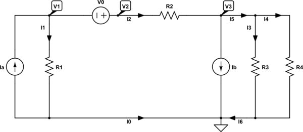
schematic

simulate this circuit – Schematic created using CircuitLab

When we use and apply KCL, we can write the following set of equations:

$$ \begin{cases} \begin{alignat*}{1} \text{I}_\text{a}&=\text{I}_1+\text{I}_2\\ \\ \text{I}_2&=\text{I}_\text{b}+\text{I}_5\\ \\ \text{I}_5&=\text{I}_3+\text{I}_4\\ \\ \text{I}_6&=\text{I}_3+\text{I}_4\\ \\ 0&=\text{I}_\text{b}+\text{I}_0+\text{I}_6\\ \\ \text{I}_1&=\text{I}_\text{a}+\text{I}_0 \end{alignat*} \end{cases}\tag1 $$

When we use and apply Ohm's law, we can write the following set of equations:

$$ \begin{cases} \begin{alignat*}{1} \text{I}_1&=\frac{\text{V}_1}{\text{R}_1}\\ \\ \text{I}_2&=\frac{\text{V}_2-\text{V}_3}{\text{R}_2}\\ \\ \text{I}_3&=\frac{\text{V}_3}{\text{R}_3}\\ \\ \text{I}_4&=\frac{\text{V}_4}{\text{R}_4} \end{alignat*} \end{cases}\tag2 $$

We also know that \$\text{V}_2-\text{V}_1=\text{V}_0\$.

Using \$(2)\$ we can rewrite \$(1)\$ as follows:

$$ \begin{cases} \begin{alignat*}{1} \text{I}_\text{a}&=\frac{\text{V}_1}{\text{R}_1}+\frac{\text{V}_2-\text{V}_3}{\text{R}_2}\\ \\ \frac{\text{V}_2-\text{V}_3}{\text{R}_2}&=\text{I}_\text{b}+\text{I}_5\\ \\ \text{I}_5&=\frac{\text{V}_3}{\text{R}_3}+\frac{\text{V}_3}{\text{R}_4}\\ \\ \text{I}_6&=\frac{\text{V}_3}{\text{R}_3}+\frac{\text{V}_3}{\text{R}_4}\\ \\ 0&=\text{I}_\text{b}+\text{I}_0+\text{I}_6\\ \\ \frac{\text{V}_1}{\text{R}_1}&=\text{I}_\text{a}+\text{I}_0 \end{alignat*} \end{cases}\tag3 $$

Now, we can set up a Mathematica code to solve for all the voltages and currents:

In[1]:=Clear["Global`*"];
FullSimplify[
 Solve[{Ia == I1 + I2, I2 == Ib + I5, I5 == I3 + I4, I6 == I3 + I4, 
   0 == Ib + I0 + I6, I1 == Ia + I0, I1 == V1/R1, I2 == (V2 - V3)/R2, 
   I3 == V3/R3, I4 == V3/R4, V2 - V1 == V0}, {I0, I1, I2, I3, I4, I5, 
   I6, V1, V2, V3}]]

Out[1]={{I0 -> -((
    Ib R3 R4 + 
     Ia R1 (R3 + R4) + (R3 + R4) V0)/((R1 + R2) R3 + (R1 + R2 + 
        R3) R4)), 
  I1 -> (Ia R2 R3 - Ib R3 R4 + 
    Ia (R2 + R3) R4 - (R3 + R4) V0)/((R1 + R2) R3 + (R1 + R2 + 
       R3) R4), 
  I2 -> (Ib R3 R4 + 
    Ia R1 (R3 + R4) + (R3 + R4) V0)/((R1 + R2) R3 + (R1 + R2 + 
       R3) R4), 
  I3 -> (R4 (Ia R1 - Ib (R1 + R2) + 
      V0))/((R1 + R2) R3 + (R1 + R2 + R3) R4), 
  I4 -> (R3 (Ia R1 - Ib (R1 + R2) + 
      V0))/((R1 + R2) R3 + (R1 + R2 + R3) R4), 
  I5 -> ((R3 + R4) (Ia R1 - Ib (R1 + R2) + 
      V0))/((R1 + R2) R3 + (R1 + R2 + R3) R4), 
  I6 -> ((R3 + R4) (Ia R1 - Ib (R1 + R2) + 
      V0))/((R1 + R2) R3 + (R1 + R2 + R3) R4), 
  V1 -> (R1 (Ia R2 R3 - Ib R3 R4 + 
      Ia (R2 + R3) R4 - (R3 + R4) V0))/((R1 + R2) R3 + (R1 + R2 + 
       R3) R4), 
  V2 -> (-Ib R1 R3 R4 + Ia R1 (R3 R4 + R2 (R3 + R4)) + 
    R2 R3 V0 + (R2 + R3) R4 V0)/((R1 + R2) R3 + (R1 + R2 + R3) R4), 
  V3 -> (R3 R4 (Ia R1 - Ib (R1 + R2) + 
      V0))/((R1 + R2) R3 + (R1 + R2 + R3) R4)}}

Now, we can find:

  • \$\text{V}_\text{th}\$ we get by finding \$\text{V}_3\$ and letting \$\text{R}_4\to\infty\$: $$\text{V}_\text{th}=\frac{\text{R}_3\left(\text{V}_0+\text{I}_\text{a}\text{R}_1-\text{I}_\text{b}\left(\text{R}_1+\text{R}_2\right)\right)}{\text{R}_1+\text{R}_2+\text{R}_3}\tag4$$
  • \$\text{I}_\text{th}\$ we get by finding \$\text{I}_4\$ and letting \$\text{R}_4\to0\$: $$\text{I}_\text{th}=\frac{\text{V}_0+\text{I}_\text{a}\text{R}_1-\text{I}_\text{b}\left(\text{R}_1+\text{R}_2\right)}{\text{R}_1+\text{R}_2}\tag5$$
  • \$\text{R}_\text{th}\$ we get by finding: $$\text{R}_\text{th}=\frac{\text{V}_\text{th}}{\text{I}_\text{th}}=\frac{\text{R}_3\left(\text{R}_1+\text{R}_2\right)}{\text{R}_1+\text{R}_2+\text{R}_3}\tag6$$

Where I used the following Mathematica codes:

In[2]:=FullSimplify[
 Limit[(R3 R4 (Ia R1 - Ib (R1 + R2) + 
     V0))/((R1 + R2) R3 + (R1 + R2 + R3) R4), R4 -> Infinity]]

Out[2]=(R3 (Ia R1 - Ib (R1 + R2) + V0))/(R1 + R2 + R3)

In[3]:=FullSimplify[
 Limit[(R3 (Ia R1 - Ib (R1 + R2) + 
     V0))/((R1 + R2) R3 + (R1 + R2 + R3) R4), R4 -> 0]]

Out[3]=(Ia R1 - Ib (R1 + R2) + V0)/(R1 + R2)

In[4]:=FullSimplify[%2/%3]

Out[4]=((R1 + R2) R3)/(R1 + R2 + R3)

Using your values we get:

  • $$\text{V}_\text{th}=-8\space\text{V}\tag7$$
  • $$\text{I}_\text{th}=-2\space\text{A}\tag8$$
  • $$\text{R}_\text{th}=4\space\Omega\tag9$$
\$\endgroup\$
3
  • \$\begingroup\$ You should be able to do this with two node equations and one supernode equation. Why do you end up with 6 total equations? That seems to be over-complicating the problem, and not following the standard procedure that's taught for nodal analysis. \$\endgroup\$
    – The Photon
    Commented May 18, 2023 at 14:29
  • \$\begingroup\$ @ThePhoton true. But did you read the first three lines of my answer? \$\endgroup\$ Commented May 18, 2023 at 14:30
  • \$\begingroup\$ Even if you want to use Mathematica, you ought to be able to set this up with 3 equations. Also students should be learning to identify the nodes properly rather than treating every place where lines join in a schematic diagram as a node. \$\endgroup\$
    – The Photon
    Commented May 18, 2023 at 14:34

Your Answer

By clicking “Post Your Answer”, you agree to our terms of service and acknowledge you have read our privacy policy.

Not the answer you're looking for? Browse other questions tagged or ask your own question.