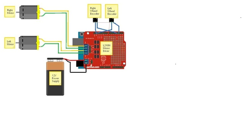
Your schematic is really small and it is hard to see.
The way I think the encoder works is:
OK1 is an optocoupler. Basically a laser diode in the left and a detector on the right. In between is a wheel with gaps in it which either lets the beam through or blocks it. Every time a gap is in the right position for the beam to reach the detector the connection between 5 and 4 closes and BROWN wire becomes 5V. You need to connect the BROWN wire to an Arduino input. Because it is 5V you can use a digital pin or an analog pin. I would probably use a digital pin. So on every step of the motor the signal on this input will change (HIGH/LOW). By counting the number of steps you will know the wheel position.
I assume that it is possible to run the motors without the encoders. If they do not run yet, you are probably not switching correctly.
Your 12V circuit for the motor is not closed. You need to change a certain pin on the Arduino to HIGH so a transistor switches and closes the circuit.
This is most probably one of the PWM pins. Those Pulse Width Modulation pins send out short bursts of HIGH to the transistor switch. By Adjusting the PWM (analogWrite(pin,0) to analogWrite(pin,255)) you can control the speed. Which pin you need to set is most probably set by the shield and you need to refer to the documentation.
Have a look here.


