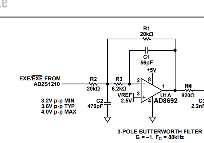
I am trying to calculate the transfer function of this circuit. Does anyone have an idea about it?
1 Answer
\$\begingroup\$
\$\endgroup\$
Does anyone have an idea about it?
It's a 2nd order multi-feedback low-pass filter followed by a single order RC low-pass filter (cut-off in your image on the right). Together they make a 3rd order low-pass filter. If you want details about the multi-feedback low-pass filter circuit try Okawa Denshi: -
They have a tool that allows you to calculate the resistor and capacitor values to suit a particular cut-off frequency.


