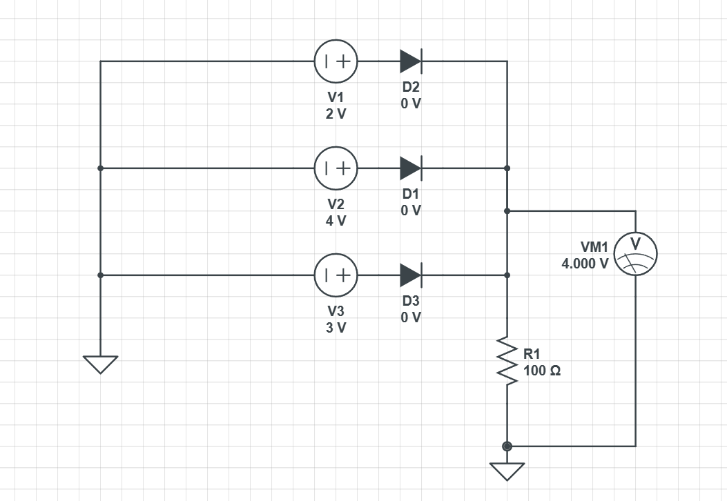
In the following circuit:
 Why is only the voltage source of 4v operating? I know that when I remove the diodes the voltmeter doesn't get any voltage but I don't know why this happens. So my question is: Why the 2v and 3v voltage sources don't contribute to the final voltage and why there is no voltage when I remove the diodes?
3 Answers
It's because D2 and D3 are non-conducting as their anode voltage (4V) is lower than their cathode voltage (2V and 3V).
This circuit is essentially an "OR-connection" of three voltage sources with the highest voltage winning. In real-life you see such circuits for battery powered devices that can alternatively be powered with a power cord, for example. In this case the voltage from the battery is "OR'd" with the voltage coming from the power cord.
When you remove the diodes there is obviously no connection between the sources and the voltmeter and thus no voltage at the voltmeter.
Your (very ideal) diodes can be in to modes :
- blocked, when the voltage is negative (ie the potential is higher at the "line" (cathode) side than at the "triangle" (anode) side of the symbol) : it behaves like an open circuit
- conducting, when current crosses the diode from anode to cathode . In this case, for an ideal diode, there is 0V voltage difference between both sides.
Note that there is no way the voltage can be positive for your ideal diode (if it where, the diode would start conducting, so the voltage would drop to 0V).
So, if your voltage (VM1) is bellow 2V, all 3 diodes will conduct, and at least the 3V and 4V voltage source would provide HUGE current (basically, you are shorting 3V with VM1<3V and 4V with WM1<4V). So the current in R1 will increase (so VM1 will increase), until VM1 reaches 2V : then the diode of the 2V will stop conducting.
But the 3V and 4V supplies are still directly connected (through the diodes) to VM<3V, so provide HUGE current (kind of short circuit), so VM will continue to increase until it reaches 3V, then the diode from the 3V supply stops conducting.
But the 4V supply is still directly connected (through its diode) to VM<4V, so provide HUGE current (kind of short circuit), so VM will continue to increase until it reaches 4V.
So if VM1 is bellow 4V, it will very quickly increase to (at least) 4V.
Now lets suppose VM1 is >4V : all 3 diodes are blocked, so there is no current flowing, so according to ohm's law, VM1=R1I=R10=0V. So if we exceed 4V, we block the current, and the voltage should become VM1=0V : this is not possible (VM1 can't be >4V and 0V at the same time).
So the only stable voltage that is possible is VM1=4V.
Note that your circuit is a very classical circuit called "power OR-ing", which is used to select the voltage source with the highest voltage at any instant (for example, if one if off, then it will select the highest voltage source among the remaining ones).
So the 2V and 3V sources don't contribute because the power OR-ing only selects the highest voltage (due to how diode work).
NB : I did all this reasoning with very ideal diodes (threshold voltage Vth=0V, as it is what you used in your simulation). If you want a somewhat more realistic model, you can consider the diodes either blocked if voltage <Vth (usually around 0.7V for common diodes), or conducting with a constant voltage drop of Vth.
As for your question why you get 0V when removing the diodes : I can't say why the simulator decided to display this value, but in practice you are just shorting all 3 supplies together. At best, 2 of them will have over-current protection, and the last one will impose it voltage. If you don't have over-current protection, you might destroy 2 supplies, and the 3rd will prevail. Or you might start a fire and burn everything (quite possible for example if 3V and 4V are lithium batteries). Or you might get some kind of "average" voltage due to internal resistances of your supplies.
So with real components, you will get something unwanted or even quite nasty without the diodes. What will happen is not modeled in the ideal components you used, so there is no way for the simulator to now (it could have displayed an error message instead, or some smoke picture, ...)
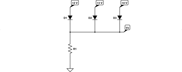
Let's simplify the schematic (without loss):

simulate this circuit – Schematic created using CircuitLab
Let's unpack the process as it might unfold over a very short period of time (less than trillionths of a second) if the three voltage supplies were to be applied simultaneously in time.
At first, before the voltage supplies are applied, \$R_1\$ is holding \$V_X\$ to ground (or \$0\:\text{V}\$.) Then the supplies are applied. Let's follow \$V_X\$ as it changes:
- For the tiniest moment all three diodes experience different but substantial voltage differences. As charges distribute within each diode, the current through them increases. But those with larger voltage differences (such as \$D_3\$) allow more current (suggested by the Shockley equation.)
- \$V_X\$ rises rapidly upwards due to the rapidly increasing current in \$R_1\$.
- At some point, \$V_X\$ reaches approximately a diode drop below the \$+2\:\text{V}\$ source supplying \$D_1\$. If the other two sources behind \$D_2\$ and \$D_3\$ didn't exist, then diode \$D_1\$ would find a balancing point where its current just matches up with what the Shockley equation says for the voltage difference across \$D_1\$ and then \$V_X\$ would settle down to this quiescent point.
- But the sources behind \$D_2\$ and \$D_3\$ do exist and the voltages across those two diodes are very much more than just "one diode drop". So, according to the Shockley equation they continue to source much higher currents than \$D_1\$. So the voltage across \$R_1\$ continues to rise due to the exponentially larger currents in \$D_2\$ and \$D_3\$. As \$V_X\$ rises still further in response to the increasing voltage drop across \$R_1\$, the voltage across \$D_1\$ decreases. According to the Shockley equation, this means less current from \$D_1\$. So \$D_1\$'s current diminishes. None of that halts the still very much larger currents in \$D_2\$ and \$D_3\$.
- Currents in \$D_2\$ and \$D_3\$ now push the voltage drop across \$R_1\$ past the point of \$+2\:\text{V}\$. And now \$D_1\$ experiences an increasing reverse-voltage across it, leaving it with only the tiniest leakage current. \$D_1\$ is technically off now and no longer plays an important role.
- The same process that just took place for \$D_1\$ now takes place for \$D_2\$, with \$D_3\$ alone now playing the role that \$D_2\$ and \$D_3\$ together played, earlier. And eventually (less than trillionths of the second, still) \$D_2\$ becomes technically off and ceases to play an important role, just as \$D_1\$, while \$D_3\$ continues to supply exponentially larger currents.
- Soon \$V_X\$ reaches the point where there is about one diode drop across \$D_3\$ (somewhere below \$+4\:\text{V}\$, but certainly high enough that the other two diodes are reverse biased) and it is here that equilibrium is reached.
That's why \$V_X\$ settles where it does.

no voltage when I remove the diodes... when you remove the diodes then there is no circuit between the voltage sources and the resistor ... you have to replace the diodes with wires \$\endgroup\$