I've got a 555 circuit hooked up to a Stylophone-type keyboard. I'd like to duplicate the audio tones—which I assume are square waves (coming out of pin 3)—a couple of times and run them through an octave-up circuit and frequency divider, and then on to a mixing circuit and see if I can get the tones to be more complex and chord-like.
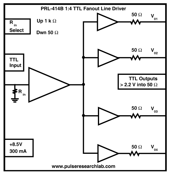
I've seen the bare-bones distribution amp circuit on this site (Active audio splitter (Line levels)) comprised of op amps. But, I found this PRL-414B diagram online and have been wondering if it could be even simpler.
Image source: Pulse Research Lab - PRL-414B - 1:4 TTL/CMOS Fanout Buffer and Line Driver
IF SO, since the output of a 555 timer is buffered, would I even need the first buffer on the left? Input and output resistors? 1K on the input? Suggestions?
OR will the hex buffer chip not accomplish what I want it to?
(Sorry about the previous version of this question. I was just happy that I managed to include an image. I have trouble with this site. I can't find a search function on it to save my life. And apparently I no longer get email prompts with regards to replies.)

