0
\$\begingroup\$

enter image description here

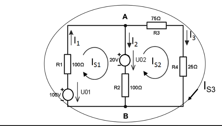
In the following diagram, the directions of both currents and voltages for voltage sources are shown. My task is to write KCL and KVL for all 3 loops, and my question concerns KVL.

I believe I am approaching KVL problems wrong, this is precisely how I think:

If we look at R2 in loop Is1, for example, we can se that both U02 and U01 are directed to it. I assumed R2's direction would be opposite to the run of Is1, since it would take the direction of the voltage with higher magnitude, U01. But in the correct KVL equation it has the same direction as the run.

Moreover I don't understand where to start the loop: should it be where the arrow is (in loop Is1 it would be R1) o do I start with the node?

Please help me understand what part of my approach is wrong and how to correct it.

Also a smaller question regarding KCL, the correct answer indicated that I1 flows out of node B, why is it so?

\$\endgroup\$
4
  • \$\begingroup\$ Do your voltage arrows show the direction of the electric field (more a continental Europe thing) or are they meant to show voltage polarity (more a UK or North American thing)? \$\endgroup\$
    – Andy aka
    Commented Oct 3, 2023 at 8:34
  • \$\begingroup\$ Nodes are 5, branches are 6, loops are 2 , cut sets are 4. \$\endgroup\$ Commented Oct 3, 2023 at 8:42
  • \$\begingroup\$ @Nare, Start the loop where ever you want. Just finish at the same place. There are only two loops to worry over with KVL. You get to pick which two. You don't need KCL to solve this. Ignore all the excess stuff thrown in there to confuse you. \$\endgroup\$ Commented Oct 3, 2023 at 10:10
  • \$\begingroup\$ @Nare, use KVL equations, Eq(0+100-r1*(is1)-20-r2*(is1-is2),0) and Eq(0-r2*(is2-is1)+20-r3*(is2)-r4*(is2),0), in Python/Sympy. Solves for the two loop currents, trivially. The rest is a distraction. \$\endgroup\$ Commented Oct 4, 2023 at 3:36

1 Answer 1

0
\$\begingroup\$

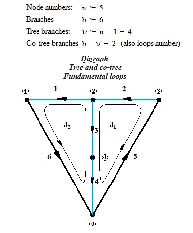
First of all, it is necessary to draw the oriented graph of the network, clearly highlighting the numbered nodes; the reference node is generally indicated with the number 0. If n is the number of nodes, b the number of branches, p the separate parts, we define The network tree is a set of consecutive branches of n-p branches. the remaining branches constitute the co-tree of the network. The branches of the tree (in blue) must be numbered in succession starting from 1 to n-1. The remaining ones, those of the co-tree, should be numbered from n to b. Once this is done, you choose the type of analysis to do. The most common is the analysis based on pairs of independent nodes. If the resulting currents and voltages are negative, this means that those currents and voltages have opposite directions to those of the digraph.

enter image description here

\$\endgroup\$

Your Answer

By clicking “Post Your Answer”, you agree to our terms of service and acknowledge you have read our privacy policy.

Not the answer you're looking for? Browse other questions tagged or ask your own question.