2
\$\begingroup\$

So I'm trying to use a zener diode to limit the voltage across a capacitor - specifically, to 2.2V.
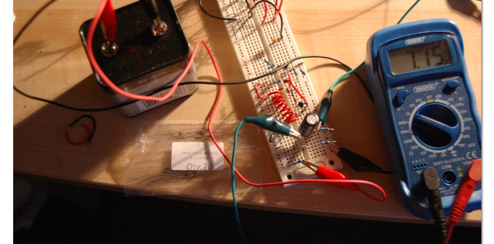
enter image description here

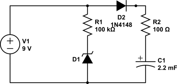
As you can see, I'm using a 9v supply. The zener is in series with a resistor - either 100 or 100k, can't quite remember which, didn't make a difference though. In parallel with this is a 16V 2200uF capacitor in series with another resistor, also 100-100k iirc.

There's a schottky to the left (in series with the zener) to prevent capacitor discharge, as well as a resistor in series with all of them (this was
schematic

simulate this circuit – Schematic created using CircuitLab

added later - had no effect).

As you can also see, the capacitor voltage is well above 2.2V, at least 7V and counting. The zener seems to be having absolutely no effect on the circuit. I've tried it with multiple ones - you can see the packet, it specifically says zener voltage 2.2V. It's definitely not a problem with frying the zener, since I have a very high resistance in series with it. What on earth could the issue be?

\$\endgroup\$
6
  • \$\begingroup\$ Please add a circuit diagram. Edit your question, hit Ctrl-M. \$\endgroup\$
    – jippie
    Commented May 8, 2013 at 20:48
  • \$\begingroup\$ 100 or 100K, which one? I suspect answer is going to depend on that. \$\endgroup\$
    – mj6174
    Commented May 8, 2013 at 20:49
  • \$\begingroup\$ It doesn't. I used both, zilch difference. \$\endgroup\$ Commented May 8, 2013 at 20:51
  • \$\begingroup\$ Edit your question and press Ctrl-M to bring up the schematic tool. \$\endgroup\$ Commented May 8, 2013 at 20:59
  • \$\begingroup\$ Good work with the schematic. The question is much more understandable now. \$\endgroup\$ Commented May 8, 2013 at 21:11

1 Answer 1

5
\$\begingroup\$

KVL rules here. The zener branch (R1 and D1) will be at the same voltage as the capacitor branch (D2, R2, and C1), which will be 9V.

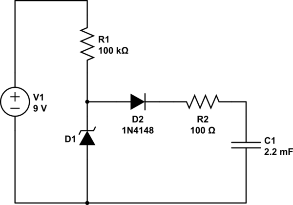
If you want the zener to limit the cap voltage, you need to move D2 to the midpoint junction of R1 and D1.

schematic

simulate this circuit – Schematic created using CircuitLab

Don't forget that D2 will eat a few hundred millivolts, meaning your cap voltage could end up as 1.6V or so.

Once you get the basic idea of how the zener clamp works, you can start playing around with the resistor values (hint: is R2 really necessary?) and see how the performance is impacted.

\$\endgroup\$
5
  • 1
    \$\begingroup\$ Plus with 100 kilohms, there is so little current through the zener that there will be much less than its rated voltage across it. You want somewhere over 1ma to get close to its rated voltage (and there is little purpose going above 5-7 ma); R1 should be in the 1k to 7k region; 5k would be a good start. \$\endgroup\$
    – user16324
    Commented May 8, 2013 at 21:16
  • \$\begingroup\$ @BrianDrummond Of course. I'm trying not to overwhelm the poor fellow. \$\endgroup\$ Commented May 8, 2013 at 21:21
  • \$\begingroup\$ Ah, yes. I could try this - however, I'm trying to limit current through the zener as much as possible to boost efficiency. I assume using a resistor for this would stop the voltage being limited? \$\endgroup\$ Commented May 8, 2013 at 22:05
  • \$\begingroup\$ Without a switching element to stop charging the capacitor, the only way the Zener can limit voltage across it is by bypassing it and wasting current, with efficiency tending towards zero. \$\endgroup\$
    – pjc50
    Commented May 8, 2013 at 22:48
  • \$\begingroup\$ Low voltage zeners aren't that great at voltage regulation, anyway. Hence the bandgap regulator, such as the ubiquitous TL431. \$\endgroup\$
    – markrages
    Commented May 9, 2013 at 6:00

Your Answer

By clicking “Post Your Answer”, you agree to our terms of service and acknowledge you have read our privacy policy.

Not the answer you're looking for? Browse other questions tagged or ask your own question.