2
\$\begingroup\$

This is my first time trying to create a circuit by myself. I have been learning different combinations of circuits such as a differential amplifier, some kind of basic circuits with an operational amplifier, a basic low/high/band-pass filter, and a 50/60 Hz notch filter.

As an electronic engineering student, I want to design an analog circuit with amplifiers for biopotential measurement (let's say ECG,) I just don't know where to start with.

First, there will be electrodes to collect the biopotential. At the end of the system, an nrf52840 microcontroller collects the amplified analog signal. Of course, I will make a PCB for the whole circuit.

  1. Should I start it from scratch or try to combine different kinds of circuits together?
  2. Is it an individual project for an intermediate learner. In which way for have a good learning experience?
  3. Aside from filtering unwanted signals and noise, and amplifying the signal, would the stability be a real concern for this circuit?
\$\endgroup\$
1
  • \$\begingroup\$ Removed the last question from your questions because it's out of scope \$\endgroup\$
    – Voltage Spike
    Commented Oct 26, 2023 at 19:59

5 Answers 5

2
\$\begingroup\$

First, there's lots of examples to start from. As Picasso once said, "Good artists copy; great artists steal."

Let the theft begin, with a search for "ekg circuit" or "ecg circuit". Most examples you will find are the 3-lead type with a driven 'leg' signal. Others are of the basic instrumentation op-amp type with 2 terminals. Sift through these and see what makes sense for you. They will usually include some kind of bandpass filter as well.

Second, before you commit to a design, build a simulation of it, at least for the analog part. There are good free Spice simulators like LTSpice and MicroCap. You may even be able to get the job done with Falstad. Falstad in particular will allow easier observation of your circuit. It's a good starting point for developing a proof-of-concept with practically no learning curve.

The 'real' Spice simulators like LTSpice, PSpice and others will provide more accurate models of your components, especially if you choose Analog Devices parts and are using LTSpice (that's part of ADI's marketing, and you benefit from their well-maintained simulator.) Expect some learning curve.

As for your specific questions about filter design, you can also work that out in simulation. Again, copy if you can, but if you're determined to develop your own, know that you will need to first understand your requirements, then choose a filter basic type (bessel, butterworth, chebyshev, elliptical) that makes the appropriate tradeoffs in passband flatness vs. cutoff slope. Fortunately, there are online tools for that too. Also, read up on filters here.

I'll mention that Falstad also has an analog filter design applet separate from the analog simulator that makes it easy to try out filters. You can cut and paste between the filter app and the circuit sim.

A tip: For an ECG/EKG, your signal rate is low enough that it would be worth investigating doing some of your filtering in the digital domain on your microcontroller. This could simplify your front end design down to just a gently-sloped anti-aliasing filter prior to the ADC input. I think a Cortex-M4 should have enough throughput. Read more here. And, an NXP Appnote doing just that.

(How would one do this "professionally"? Probably using Matlab and Simulink. That's a whole 'nother ball of wax.)

Once you're satisfied with your simulation, then it makes sense to lash up a prototype and test it to confirm what you see in the simulation. Build this with care, taking into account your concerns about noise. This is also where you get to play with how to make good skin contact. A conductive gel helps - you can even make your own from an aloe plant and table salt.

Also, for your first go don't use line power, use a battery. Even an 'isolated' supply will have some AC leakage that will couple into your measurement, and there is some safety concern too. (Note that medical supplies are designed with lower leakage, for both signal and safety reasons.)

Once you have all that settled, you'd capture your design in a schematic, create a layout and make your board. KiCAD is a free EDA suite that can help do that.

\$\endgroup\$
3
  • \$\begingroup\$ A good overview over the steps. However, one remark. Eagle has been discontinued and was already lacking in support for years compared to alternatives like KiCAD. \$\endgroup\$ Commented Oct 26, 2023 at 19:01
  • 1
    \$\begingroup\$ Switched it to KiCAD. Thanks! \$\endgroup\$ Commented Oct 26, 2023 at 19:27
  • \$\begingroup\$ @hacktastical Thanks for your information. They are so helpful. Right, the first thing I should work on is to learn how to make a filter from the basic. All complicated designs are built from those basic designs. \$\endgroup\$
    – TSLee
    Commented Oct 31, 2023 at 15:07
1
\$\begingroup\$

For wireless battery-powered circuits with a single electrode - a good starting point - a differential amplifier is not necessary. "GND" is the reference electrode.

ECG is a good starting point, since it's a strong signal. Strong enough to be captured by electromechanical devices (!). ECG's discovery was done in a setup that consisted of two buckets of saline solution, into which the subject put their legs, and a sensitive galvanometer with optical pointer (optical lever).

If you want a very strong ECG signal, the saline buckets would be an excellent choice. But never ever connect them to any power supply wired to mains. Battery supply only, and no wired connections to any other mains-powered equipment. Needs to be wireless one way or another. An optical lever is one way of "wireless transmission" :)

\$\endgroup\$
2
  • \$\begingroup\$ Getting a good signal is key - dealing with noise sources on top of learning circuits is a lot to take on. If it takes saline buckets to get a good signal, its worth the trouble. I'd not have thought of that. \$\endgroup\$
    – glen_geek
    Commented Oct 25, 2023 at 23:25
  • \$\begingroup\$ @glen_geek These days getting a galvanometer sensitive enough is a bit of a problem - most of them are old or very expensive (or both). But yeah, saline buckets give enough signal that some audio digitizers that are quiet enough can acquire the signals directly (ideally after shorting bypassing the coupling capacitor). I have a no-name USB audio digitizer and it acquires ECG OK-ish after tweaking the passive input network a bit. \$\endgroup\$ Commented Oct 27, 2023 at 13:33
1
\$\begingroup\$

I recommend splitting the design into different modules, and then design, prototype, and test each module individually -- maybe starting in order of risk or importance (e.g., if you're building an ECG system, if you can't collect and amplify signals from the heart, there's no point in designing a notch filter, as you'll have nothing to use it on). After that, build the entire system from left to right, making sure that each stage works in situ before moving on.

What you're trying to avoid is building a huge system, finding out it doesn't work, and having a nasty problem to debug that's hard to find.

\$\endgroup\$
1
\$\begingroup\$

To add to the other very good answers already given: While I understand the urge to design that circuit from scratch, I would advise using a dedicated "Analog Front End for ECG" IC. I have worked for over a decade on brain-computer interfaces and with custom-made ASICs for the front-end part, and I am still caught by surprise from time to time by some effects. Most people are unaware of influences like electrode impedance mismatch, current leakage/OCPs (relevant for electrochemically coupled electrodes), or why an instrumentation amplifier architecture is preferred over a differential one. Building discrete circuits for ECG works because ECG is such a strong signal. But if you aim for other e.g. EEG, good signal-to-noise is much harder to achieve.

P.S. we had a lab course were students had to built their own EMG recorder. Later one of the students joined our chair and tried to build a pong demonstrator based on his project. It worked fine in the lap but only recorded garbage at the exhibition - turned out that the power supply of the theme park next to the exhibition was too strong or the CMRR of the circuit too bad.

\$\endgroup\$
1
\$\begingroup\$

Should I start it from scratch or try to combine different kinds of circuits together?

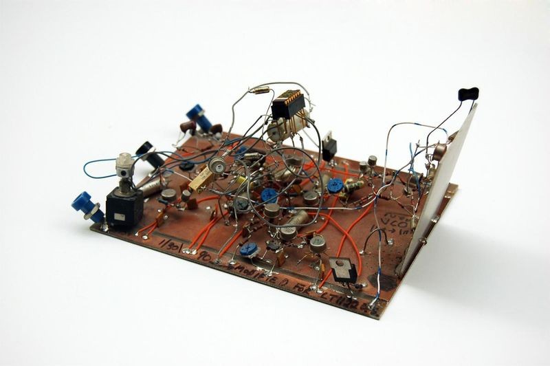
Depends on if you can prototype it, sensitive circuits such as ECG need a good ground plane and low capacitance so a PCB would be recommended. You can also just solder things together like Jim Williams.

enter image description here

Is it an individual project for an intermediate learner. In which way for have a good learning experience?

Learn new skills and make sure you learn enough to finish the project

Aside from filtering unwanted signals and noise, and amplifying the signal, would the stability be a real concern for this circuit?

Stability in terms of what? Mechanical stability: If you want it to be mechanically robust, then a PCB would be best. Temperature stability? Use thermal control. Noise and crosstalk will be a concern. Get Electromagnetic Compatibility Engineering by Henry Ott and read it.

\$\endgroup\$

Your Answer

By clicking “Post Your Answer”, you agree to our terms of service and acknowledge you have read our privacy policy.

Not the answer you're looking for? Browse other questions tagged or ask your own question.