2
\$\begingroup\$

I am new to analogue electronics and I am still learning about op-amps. I use the most common circuit for amplifying a photodiode's signal to measure it with an ADC: Default photodiode amplification
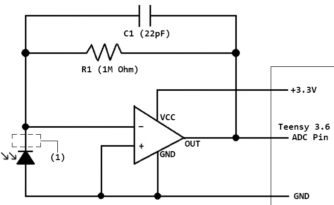
Amplification gain is 1M, the 22pF cap in parallel is for damping oscillating noise when the impulse comes in. I got some 50Hz noise in the signal due to the diode's cable is a .5 meters long flat ribbon cable, that's a problem, but not for this thread (if anyone knows how to filter that I will listen ;) ).

Now, when I touch the solder joint on the output of the diode (1), the 50Hz noise gets massively amplified. I don't want this to be gone, it will be isolated later, but I want to know why.

My guesses:

a) I'm a big resistor, adding additional resistance to R1 (1M) and so increasing the gain of the amplifier (keyword biopotential)

b) I'm a big antenna, receiving 50Hz noise of my surroundings and the op-amp amplifies that, so the signals do have different sources.

Thanks for any information!

Some background: I'm a computer science master student writing my thesis about hand gesture detection with infrared measurements through the skin, therefore the measured signals are rather small and need amplification.

[edit]

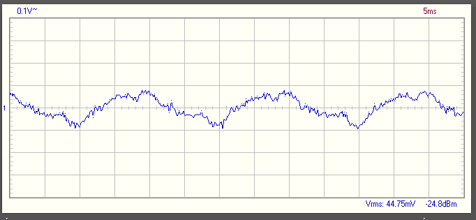
I was able to measure my own body's 50Hz signal with my oscilloscope, thank you all!

Signal of my body

\$\endgroup\$
3
  • \$\begingroup\$ (b) doesn't seem likely. It's probably due to your capacitance. Poke it with a wooden stick and see what happens compared to a plastic non-conductive stick. \$\endgroup\$
    – DKNguyen
    Commented Oct 11, 2019 at 14:13
  • \$\begingroup\$ you are in the near-field of the 50Hz power in the walls and power cables. You are an excellent near-field antenna, being a large piece of salty meat. \$\endgroup\$ Commented Oct 12, 2019 at 4:00
  • \$\begingroup\$ Thank you both! Being a salty piece of meat searching for sticks to poke my electronics, I might finally get anything near understanding that the world around me is much too big for me to understand... ;D \$\endgroup\$
    – Dommar92
    Commented Oct 12, 2019 at 9:27

2 Answers 2

2
\$\begingroup\$

Your option b is correct.

Your body is mostly insulated from ground, so it acts like a plate of a capacitor. The other plate is the rest of the world, or better, the portion of world somewhat near you.

A part of this other plate is, for example, the mains wires in the ceiling or walls. Since the voltage in them oscillates at 50 Hz, and you and them make a capacitor, then some of this voltage is present also on your body. When you touch a high impedance node, such as the cathode of the diode, this voltage is injected in the circuit, amplified and you can see it on the output.

Try to touch the circuit ground node as well, and you will see the noise decrease dramatically.

And use a shielded cable, not a ribbon cable, or even better put the amplifier next to the diode.

\$\endgroup\$
2
  • \$\begingroup\$ That does sound plausible. You are right, touching the ground with my other hand removes the noise completely (also dampens the signal a bit). I expect a ferrite core to arrive next week to apply to the cable, but I think it just filters high outgoing frequencies, no 50Hz incoming (am I wrong?). Unfortunately, I don't have enough space to mount the amplifiers (4 ICs with 14 resistors and 14 caps) directly to the diodes but will test the whole thing with a much shorter ribbon cable next week. \$\endgroup\$
    – Dommar92
    Commented Oct 11, 2019 at 14:29
  • \$\begingroup\$ @Dommar92 A ferrite filters high frequencies no matter whether they're incoming or outgoing; it doesn't know the difference. \$\endgroup\$
    – Hearth
    Commented Oct 11, 2019 at 14:32
1
\$\begingroup\$

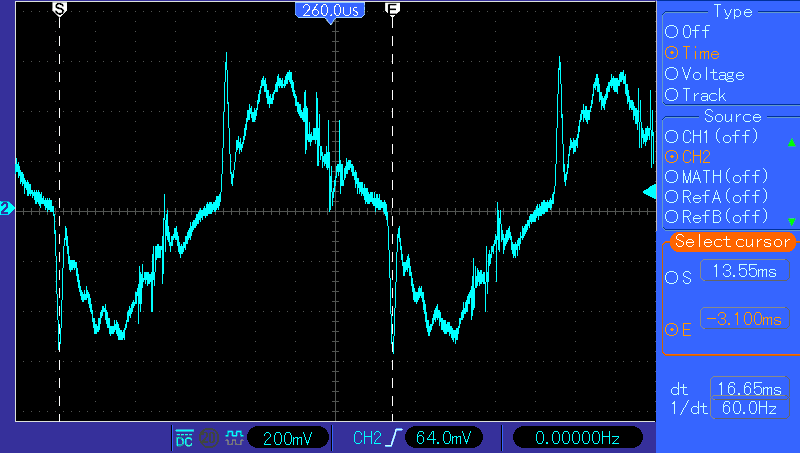
When I touch (grab) the tip of my oscilloscope probe, I get the following waveform. The 'scope is grounded via its power supply, but I'm only touching the probe tip. Note that the AC power in my region is 60 Hz, not 50 Hz: oscilloscope probe tip to hand
Note that the primary wave has a 60 Hz period, but has a very jagged wave shape....the AC power source is certainly not so "unclean", and is much closer to a sinusoidal wave.
This unclean waveshape is a big clue that capacitive-coupling is involved. My body capacitance couples higher frequencies more efficiently to the probe, which is terminated in a 1MEGohm resistor inside the 'scope. So irregularities in the 60 Hz wave are made more prominent.

Waveform peaks are +/- 600mV, indicating that 0.6 microamp is available from my body capacitance. This magnitude of current would by injected into the "-" node of your op-amp circuit, creating 600mV peak amplitude at the op-amp output.

\$\endgroup\$
1
  • \$\begingroup\$ I would upvote, but I don't have enough rep. Thank you for making the actual signal visible! \$\endgroup\$
    – Dommar92
    Commented Oct 12, 2019 at 9:34

Your Answer

By clicking “Post Your Answer”, you agree to our terms of service and acknowledge you have read our privacy policy.

Not the answer you're looking for? Browse other questions tagged or ask your own question.