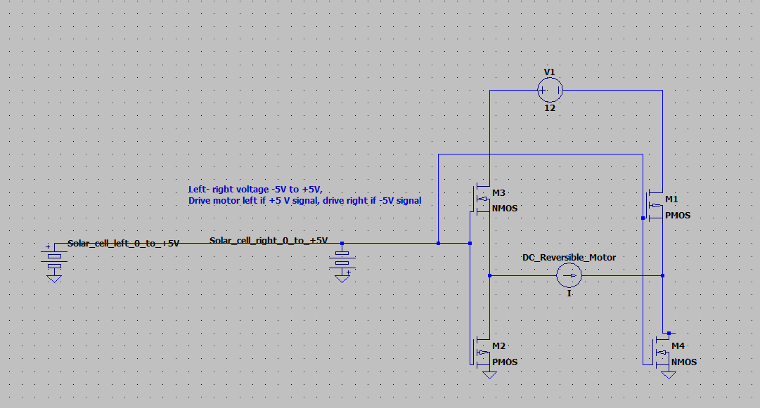
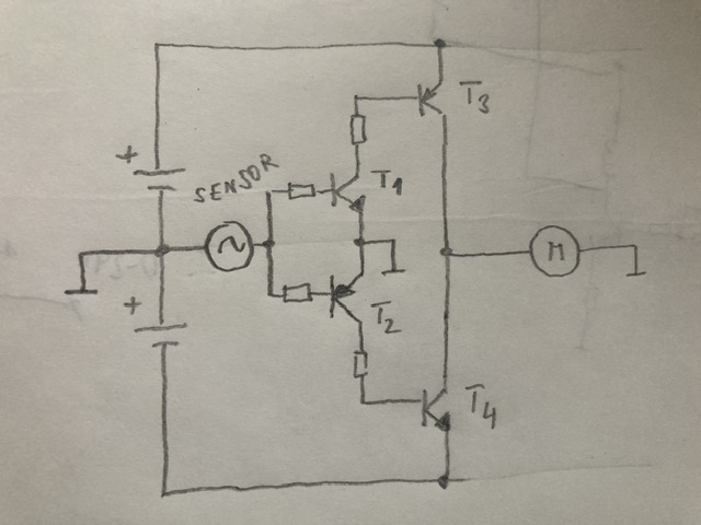
 I am not an electrical engineer (aerospace trying to be electrical) and am building a solar tracker. TLDR Goal is to turn on M3 and M4 if signal is positive, and M1 and M2 if signal negative to drive motor rotation direction. Using a technique similar to the Parker Solar Probe, I am using 2 solar cells to generate a signal to drive a motor left and right, and 2 for a motor up and down. The solar cells oppose each other electrically (+ on one to - on the other, and - to +), and are on opposite sides of the array, so if the sun is to the right, I get a small positive voltage, and if the sun is to the left, I get a negative voltage. Now, these cells are too small to drive the DC motor, so I need either relays or a bridge circuit to increase the power for the solar cells to activate the motor. I don't want to use a microcontroller and prefer analog if possible.
I understand how a bridge circuit can be used to reverse a DC motor, but I understand a bridge assumes the required gate voltages are all positive. Is there a way to drive a motor one way with a small positive signal voltage, and the opposite way with a negative gate voltage? The MOSFET switching on with a negative gate and off at zero is what I need but don't see how.
Edit: on further research it looks like a bidirectional P-channel MOSFET would switch a negative voltage with a negative gate voltage.

