0
\$\begingroup\$

Followup to this question.

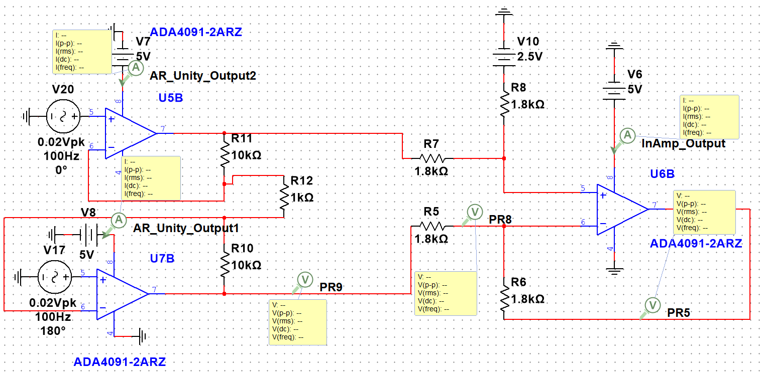
I have an instrumentation amplifier.

enter image description here

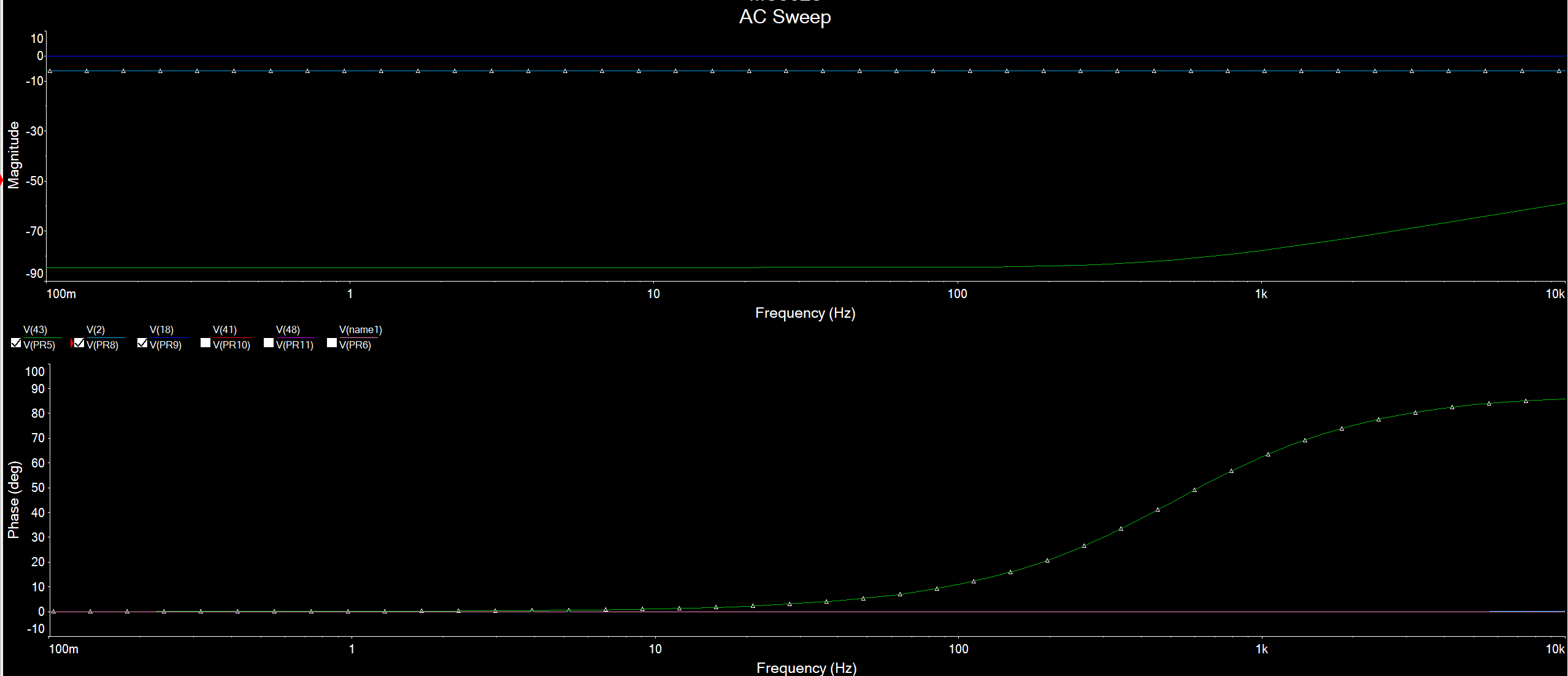
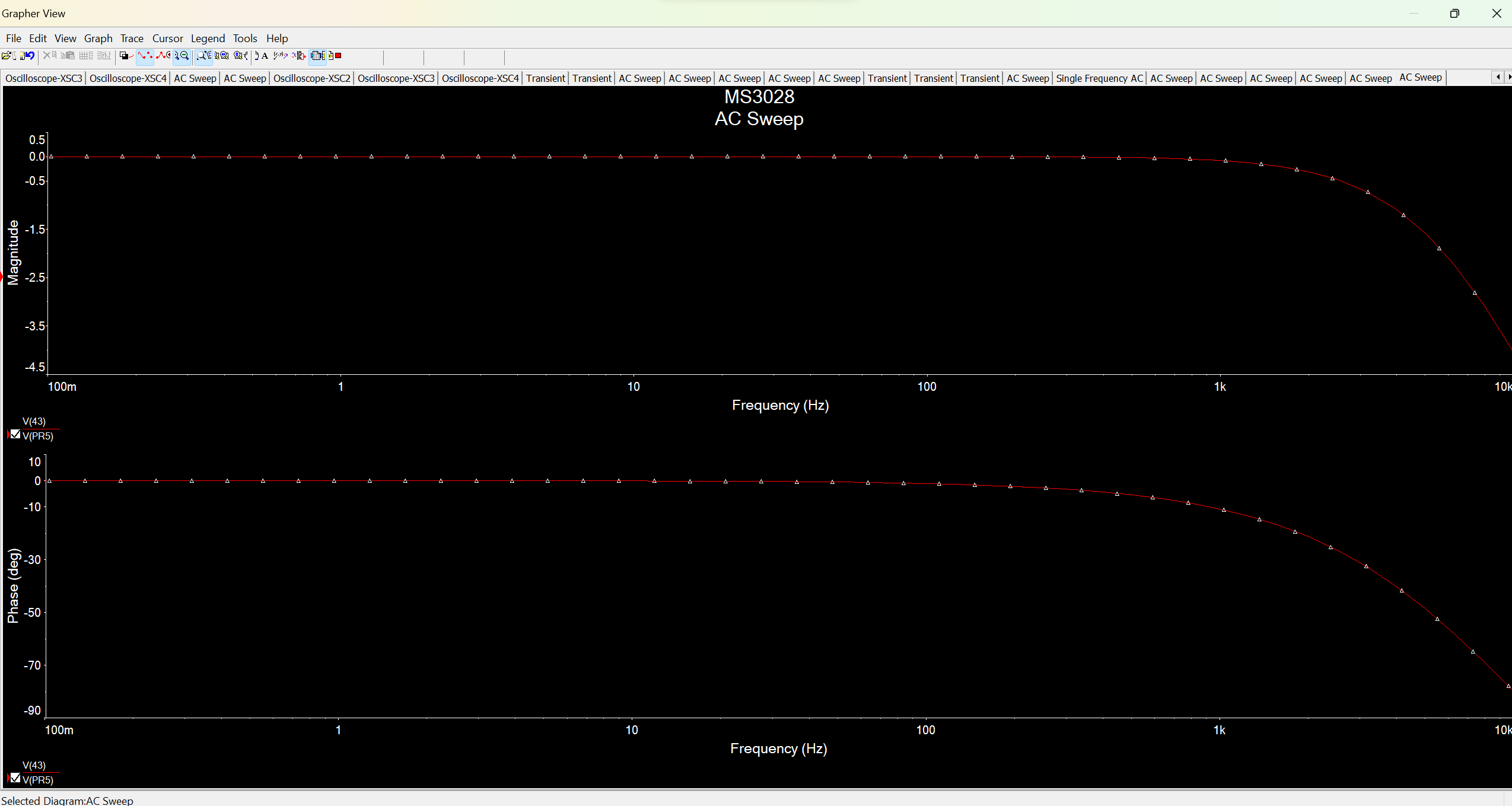
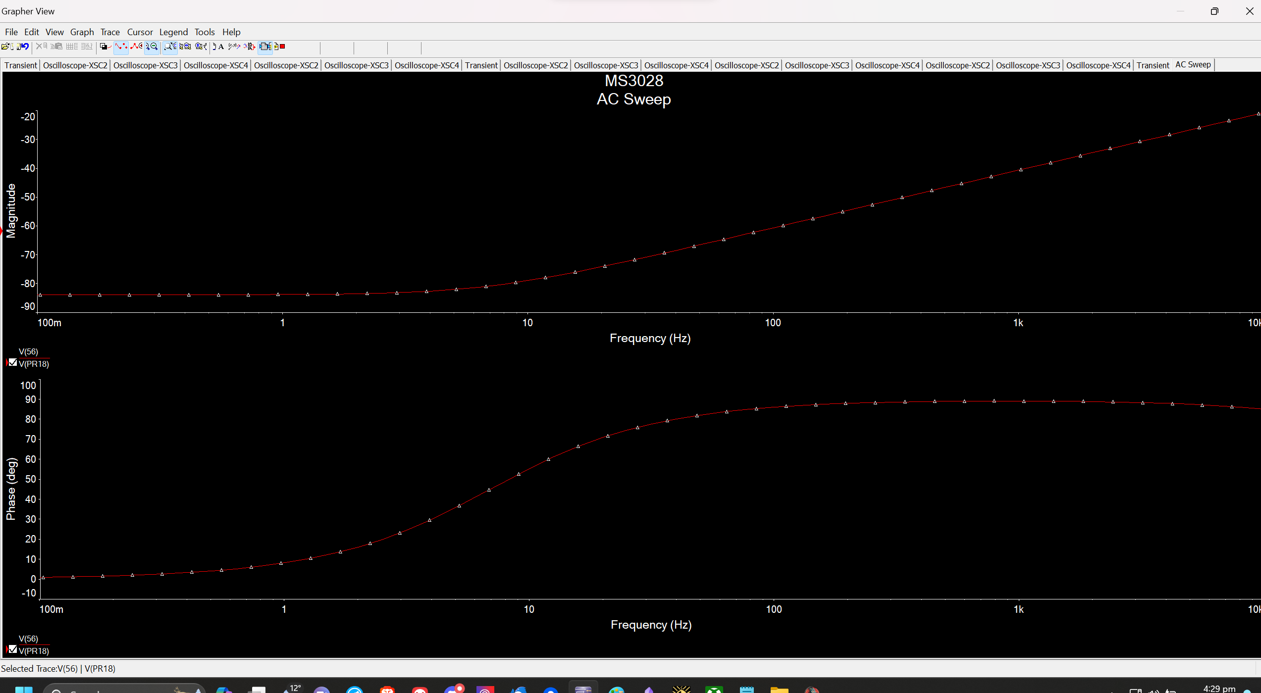
When conducting an AC Sweep, this is the response. enter image description here

There are two issues with this. Firstly, the signal magnitude is far too low. Secondly, the signal somehow grows on higher frequencies.

I lack any reactive passive components and reactance of the op-amp used (the ADA4091) is not significant until exceeding 100kHz. If there is a parameter in the op-amps that would affect this, I am unaware of it.

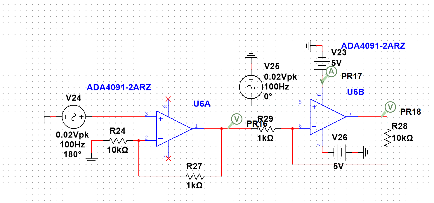
Bode plot with PR8 and PR9 included, points within the Instrumentation Amplifier.

enter image description here

Addendum: The input voltages (V17 and V20) are offset by +2.5V. Unfortunately Multisim does not display that properly. Thank you to Andy aka for reminding me to specify that.

Addendum 2: I've isolated the issue to the latter half of the circuit, as disconnecting the two shows that the first half acts within reason with a magnitude of around -1dB for an AC Sweep, while the latter half still has a -100dB loss.

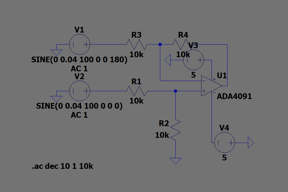
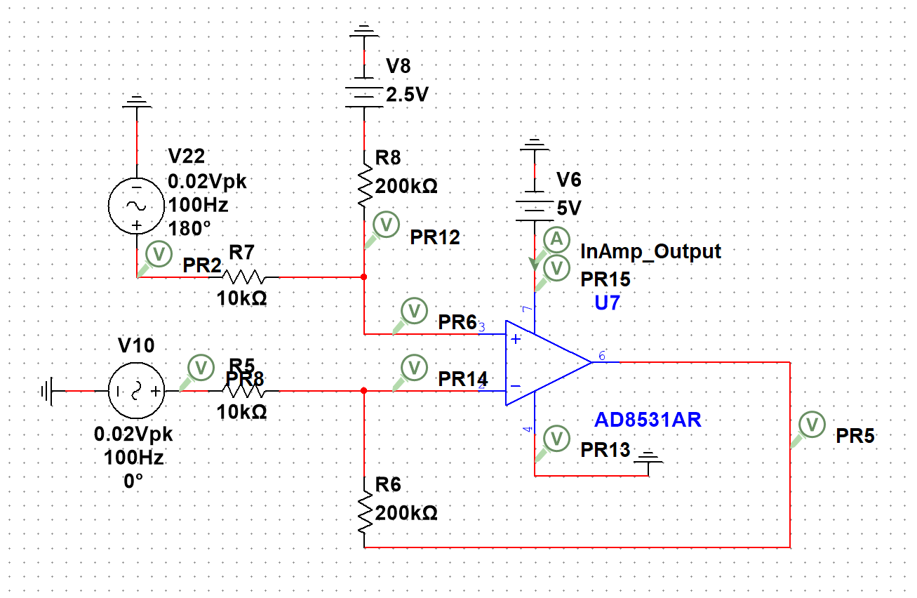
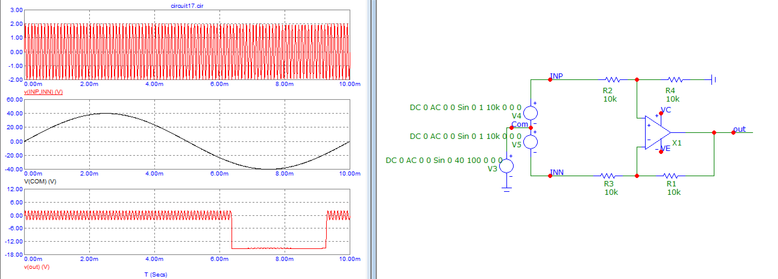
Based on suggestions that Multisim is not as commonly used, I simulated the latter half of this circuit (which is just a differential amplifier) in LTSpice. I removed all offsets and provided a +5V and -5V voltages as inputs.

enter image description here

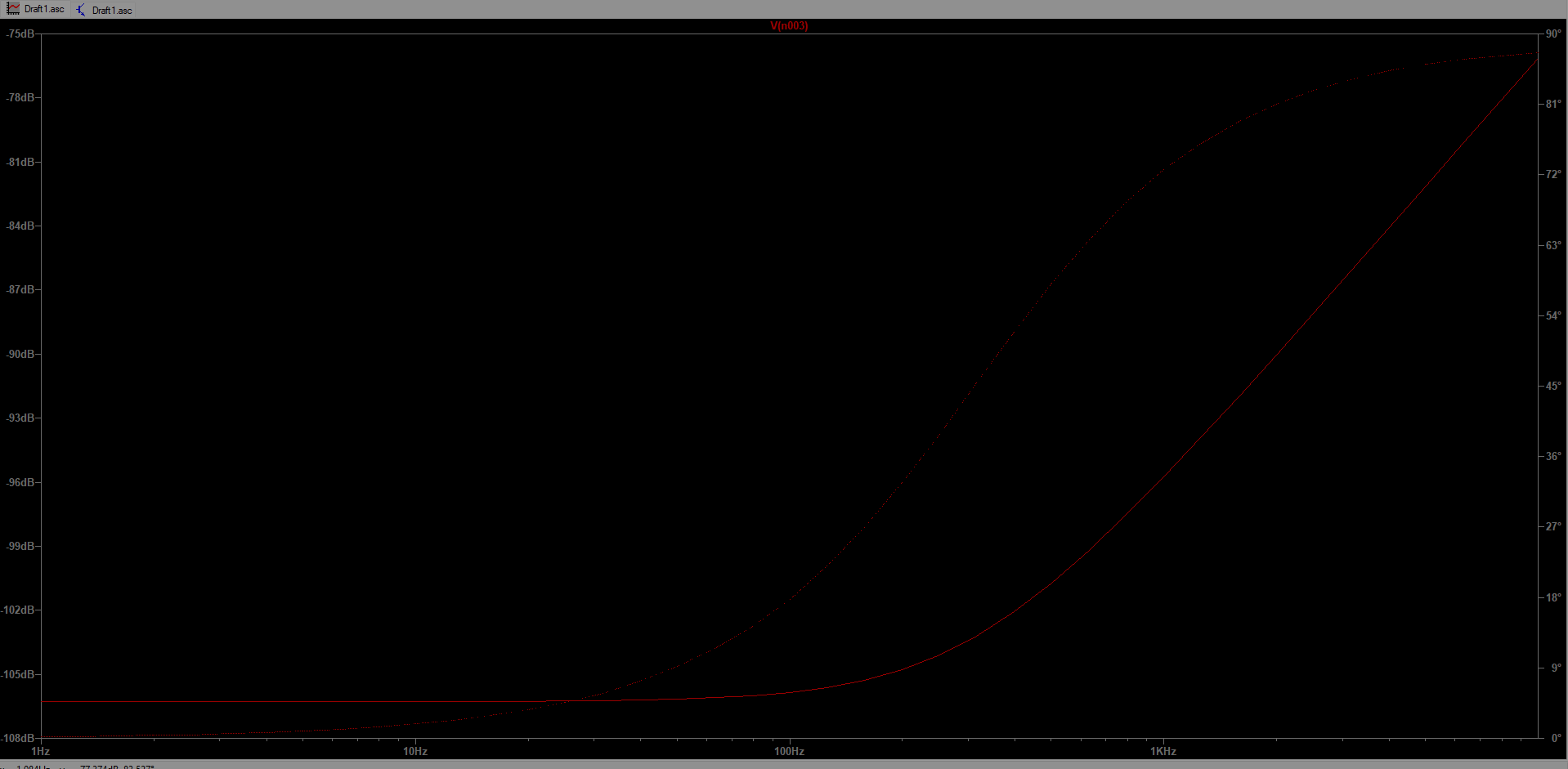
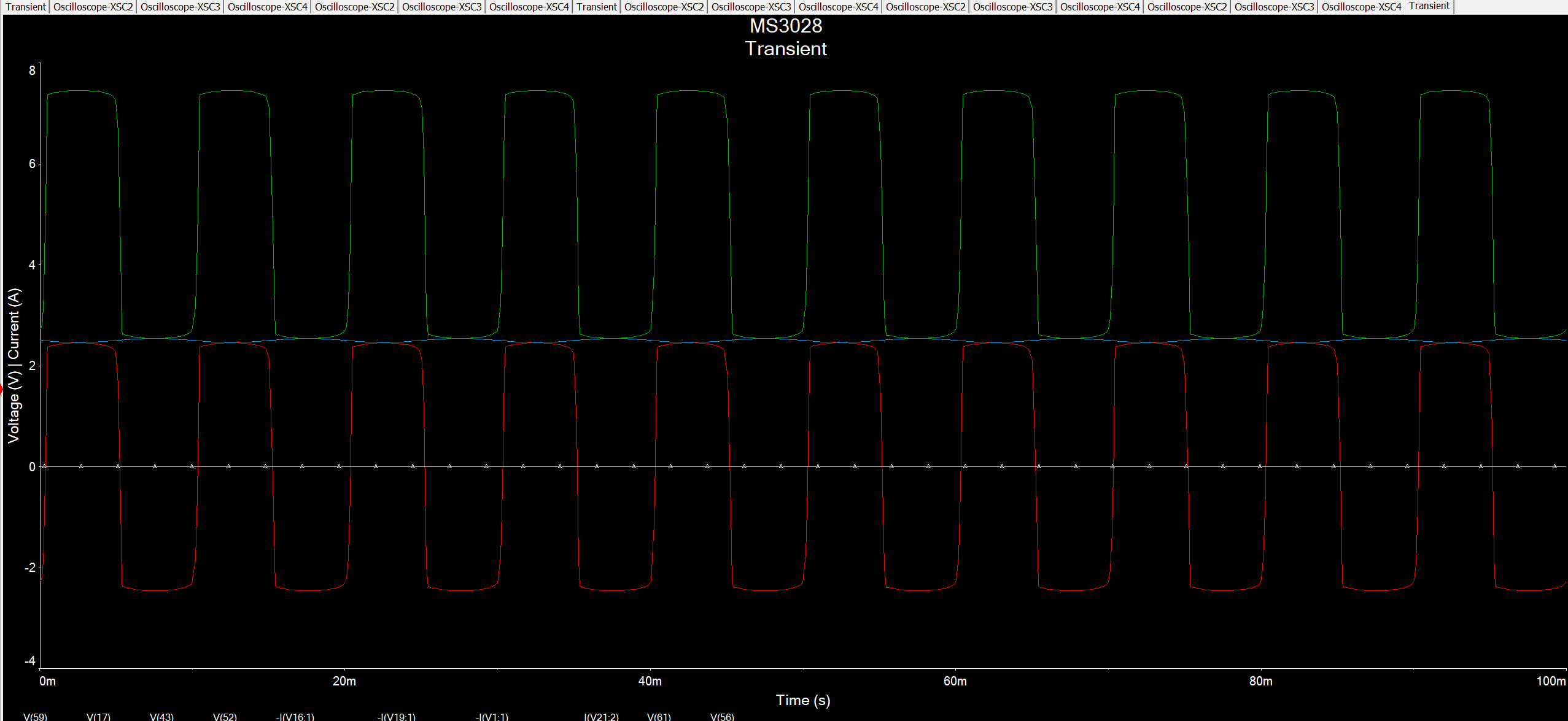
The AC Sweep remains unsatisfactory despite a reasonable transient response.

enter image description here

enter image description here

One thing of note is that the power source powering the Op-Amp (An ADA4091) is returning the following response in AC Sweeps:

enter image description here

The LTSpice simulation file in question: https://ufile.io/640sx0l3 (I can put it somewhere else if this site is not too familiar with ufile)

Addendum 3: Other things attempted include

  1. Changing values and ratio of resistor. Changing values of resistor while maintaining ratio did not improve magnitude. Increasing gain of system with resistor ratio changes did improve the magnitude to an extent in the AC Sweep (I was able to get -20dB) but due to application issues, the gain of the diff. amplifier cannot be over 20.

enter image description here

  1. Change input voltage to 5V and -5V. No change observed.

  2. Change input voltage to it's own loop. This improve the magnitude greatly, but the output voltage became dependent on the voltage source, which varied significantly.

enter image description here

enter image description here

enter image description here

  1. Change input offset from 2.5V to 0V. This had no effect.

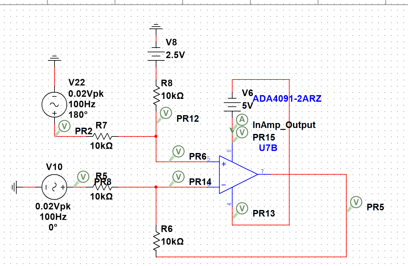
  2. Attempt to switch to 2-opamp Instrument Amplifier circuit. Magnitude was similarly low.

enter image description here

enter image description here

\$\endgroup\$
7
  • \$\begingroup\$ First of all check the DC conditions. The output you are seeing is extremely low and probably due to signal leaking through the feedback components. \$\endgroup\$ Commented Dec 22, 2023 at 17:33
  • \$\begingroup\$ What are the DC conditions in this context? I thought the InAmps should have filtered all DC voltage save for the offset provided by V10. \$\endgroup\$ Commented Dec 22, 2023 at 17:40
  • \$\begingroup\$ If the DC conditions are not correct the amplifier could be saturated and not operate as you intend. \$\endgroup\$ Commented Dec 22, 2023 at 17:48
  • \$\begingroup\$ Thank you, but what are the DC conditions in this context? \$\endgroup\$ Commented Dec 23, 2023 at 12:46
  • \$\begingroup\$ Are you sure that the input voltages are set? Perhaps if Multisim doesn't display them right, it also doesn't set them right. Probing the inputs may be useful. \$\endgroup\$
    – John Doty
    Commented Dec 23, 2023 at 12:55

3 Answers 3

1
\$\begingroup\$

enter image description here

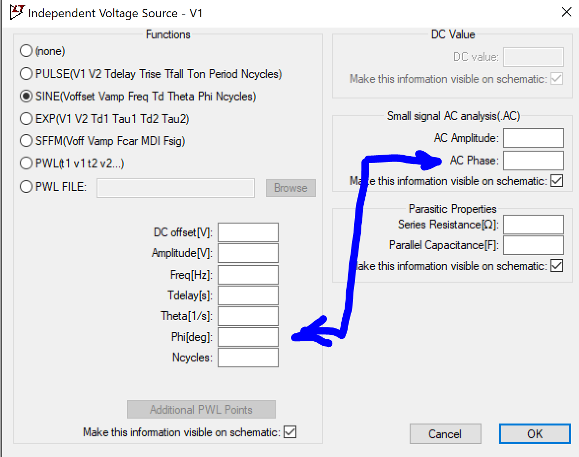
Your two sources spec "AC 1", so in AC mode they have the same phase. You are simulating the common mode rejection of the differential amplifier. As expected, CMRR decreases with rising frequency, so the "gain" you plot starts from very low (high CMRR) at low frequency and then rises as frequency increases.

Solution: define one of the AC sources as "AC -1" so you have an AC differential signal at the input.

Note the phase specified in SINE(...) is only for transient and is ignored in AC mode. In fact everything you put in the left side of this box is only for transient, it will be ignored in AC and DC modes. For AC you can specify amplitude and phase, likewise these are ignored in transient and DC modes.

enter image description here

Better solution: use a bunch of defines like so

.define test_cmrr 0
.define test_diff 1
.define test_psrr 0

Then for each source you set the AC value to the relevant variable. For example these two input sources would have "AC test_cmrr+test_diff/2" and "AC test_cmrr-test_diff/2".

Power supply sources have "AC test_psrr". Then you can change a define, and that sets your sources properly to plot what you want.

Or you can put a voltage source for the common mode, and two voltage sources for the differential mode (same definition for both but one has polarity switched), which is a lot more convenient if you want to make a transient sim with a non-constant common mode, or signals with different amplitude/frequency on both common and differential modes, for example to check for saturation.

Here is a crummy model of LM358 which uses a spice current source to model the input stage tail current source, so it allows unrealistic input common mode:

enter image description here

\$\endgroup\$
2
  • 1
    \$\begingroup\$ I implemented your suggestions in the NI Multisim context by looking for an "AC Analysis Phase" setting, which allowed the system to operate at 6dB. \$\endgroup\$ Commented Dec 26, 2023 at 13:15
  • 1
    \$\begingroup\$ Great! Note gain is Vout/Vin, but Vin is the differential voltage between the two inputs. So if you have a source with "AC 1 Phase 0°" and another with "AC 1 Phase 180°", your input amplitude is actually 2V not 1V. So if AC analysis says 6dB at the output, your real gain is 0dB. To get the actual gain you must set both sources to "AC 0.5" with correct phase, so they sum to Vin=1V differential, then the AC output gives the gain of the amp directly. \$\endgroup\$
    – bobflux
    Commented Dec 26, 2023 at 13:50
1
\$\begingroup\$

There are two issues with this. Firstly, the signal magnitude is far too low.

Your input signals must be centred around half the op-amp supply. You op-amp is powered from 5 volts and 0 volts and therefore you need to centre the input signals to 2.5 volts or they might not won't work correctly. Try looking at the transient response and you will see ugly half wave rectified sinewaves at the outputs or, maybe you won't see anything if the model is designed to ignore any input signal close to 0 volts.

Secondly, the signal somehow grows on higher frequencies.

This also may be due to your lack of input biasing.

\$\endgroup\$
5
  • \$\begingroup\$ I should have specified that my input signals from V17 and V20 are centered around 2.5V. My bad. I should have also specified that the simulation runs as expected under the transient response. I will edit the question to better reflect this, thank you. \$\endgroup\$ Commented Dec 22, 2023 at 17:39
  • 2
    \$\begingroup\$ Well, if you edit your question, it makes my answer look stupid so, please don't do that. If you must do something, add an addendum that clearly shows you have rehashed the circuit diagram and connect your input signal negatives to +2.5 volt. \$\endgroup\$
    – Andy aka
    Commented Dec 22, 2023 at 17:41
  • 1
    \$\begingroup\$ @HFOrangefish Look into your input sources to make sure you have the AC amplitude set to 1 or unity. I can't help on your actual sim tool because it's not what folk normally use (LTspice or microcap for example). \$\endgroup\$
    – Andy aka
    Commented Dec 22, 2023 at 19:04
  • \$\begingroup\$ Based on your suggestions, I've attempted to simulate the latter half (diff amplifier part) circuit in LTSpice too, with a similarly poor response. Should I put that as a separate question or should I edit this question? \$\endgroup\$ Commented Dec 24, 2023 at 22:46
  • 1
    \$\begingroup\$ Add it to the question as addendum #2 please @HFOrangefish \$\endgroup\$
    – Andy aka
    Commented Dec 24, 2023 at 23:00
0
\$\begingroup\$

One thing that can appear to be frequency response problems is slew rate issues. As frequency goes up, slopes go up, too, requiring higher slew rates. So, something that works for small output signals may not work for large output signals.

Peek at the slew rate of your final output op amp, and make sure the peak value of the derivative of you output "fits".

\$\endgroup\$
3
  • \$\begingroup\$ The slew rate is 0.46V/us, which is adequate for my operations. My peak-to-peak should be around 2V, which would take the op-amp 4.3us to reach. My understanding tells me that the system should stop functioning around 100kHz, but it's not functioning in AC Sweeps of 100Hz and below. If anything, performance increases when frequency increases. \$\endgroup\$ Commented Dec 24, 2023 at 23:54
  • \$\begingroup\$ @HFOrangefish .46v/us =460000V/s, about 0.5*10^6. The peak derivative of a 100kHz sine wave at 2V (assuming that's what you'd like output) is about 1.3x10^6V/s -- almost 3 times higher. You are having slew rate issues, but you might not be having only slew rate issues. \ \$\endgroup\$ Commented Dec 25, 2023 at 20:11
  • \$\begingroup\$ But I'm not planning on running the circuit with a 100kHz signal. I'm aware that the op-amp's slew rate is inadequate for 100kHz but my signal is within the 100Hz range, not 100kHz. \$\endgroup\$ Commented Dec 25, 2023 at 20:42

Your Answer

By clicking “Post Your Answer”, you agree to our terms of service and acknowledge you have read our privacy policy.

Not the answer you're looking for? Browse other questions tagged or ask your own question.